Move Close
Welcome to zx14ninjaform.com!

You are not logged in.
New Topic Reply
Next Page

Page: 1

Previous Page

Thread: LCD-200 Setup and Functions

Created on: 10/12/16 12:04 PM

Replies: 8

Rook


Rook's Gravatar

Joined: 03/28/09

Posts: 20574

LCD-200 Setup and Functions
10/12/16 12:04 PM

LCD-200 Setup and Use
The LCD has been superseded by the POD-300. One advantage of the POD-300 is that it is easier to view with larger displays and a brighter backlight. The LCD-200 is still very useful and perhaps more fetching to the eye. It’s a nice device and if you already own one, it probably is not worth upgrading to a POD-300 until you give the LCD a good try.

I’ve arranged this tutorial in order of importance so that LCD-200 users can test settings and functions as they are most likely to need them. The register that follows is based on the Main Menu screen of the LCD-200 and includes all of the headings and subheadings in this tutorial.

LCD Configuration
Touch Screen Configuration………………………steps 1 through 8
LCD Information……………………………………steps 9 and 10
Backlight…………………………………………….steps 11 and 12
Colors ……………………………………………….steps 13 through 16
Exit
Switching Main Menu/Gauge Screen ……………steps 17 and 18
Gauge Setup
Template Selection………………………………….steps 19 and 20
Bar Gauge Setup……………………………………steps 21 through 32
Analog Gauge Setup ……………………………….steps 33 through 45
Digital Gauge Setup…………………………………steps 46 through 54
Begin/Stop Log
Formatting the Memory Card………………………steps 55 and 56
Recording Log Filessteps…………………………..steps 57 and 58
Log File Manage
Selecting Log Channels…………………………….steps 59 through 67
Log File Playback……………………………………steps 68 and 69
Viewing Complete Data from Log Files……………between steps 69 and 70
Device Setup
PCV Functions
- Send Map…………………………steps 70 through 76
- Throttle Position Calibration………………steps 77 through 80
- Wheel Speed Calibration………………….steps 81 through 86
- Gear Position Calibration………………….steps 87 through 92
- PCV Device Information……………………steps 93 and 94
Wideband 2 / AutoTune Functions
- AFR and RPM Signal Settings……………steps 95 through 102
- Analog Channel Input Configuration……..steps 103 through 117
- WB2 / AT Device Information……………..step 118
- O2 Sensor Test……………………………..steps 119 through 122

Do First:
Install the LCD-200

LCD Configuration
Touch Screen Configuration

1. Turn the ignition key ON. The LCD will display whatever set of gauges is currently selected. You will select the gauge layout and channels of your preference but first, you will need to calibrate the touch screen so that it will react properly to location of touch.

If the touch screen is out of calibration, it may not react properly to touch at all so you may use the red buttons to navigate the procedure. The top small button may be used to cancel an operation. The middle button is a joystick that is used to toggle up/down and left/right over menus and it may also be used as a cancel button if it is pressed straight in. The bottom button is used to enter chosen selections and proceed.


2. Press the ENTER button to open the main menu.


3. Toggle to LCD Config.

4. Toggle to Touch Panel.


5. Toggle to Start.


6. Press the ENTER button to start the touch screen calibration procedure. You will see a target appear in the upper right hand corner of the touch screen.


7. Use a fine point object to lightly touch the center of the target. You do not need to press very hard at all. A second target will appear at the lower right corner of the touch screen. Touch its center with the fine point object as before. A total of 5 targets will appear around the screen and they all need to be touched one time and in the order they appear. Do not touch any target more than one time. If you touch a target multiple times, the display will advance registering each touch as the center location of the last target. If this happens, you will need to toggle to Cancel and press the ENTER button to start over.


8. After the fifth target has been touched, the touch screen will be calibrated and you may use your finger or a touch screen stylist to navigate the menus.

Touch OK in the Calibration Complete box. If you are using your finger, it is more of a press than a touch. If using a stylist, try to touch near the top border of buttons and selections.


LCD Information

9. Touch the LCD Info button on the LCD Configuration screen to open the LCD Info box.


10. The LCD Info box contains identifies what user data is entered in the LCD-200 should you ever need to refer to it for possible updates.

Touch EXIT to close the LCD Info box.


Backlight

11. Touch the Backlight button on the LCD Configuration screen.


12. The LCD Brightness Control box opens.

Use the LESS and MORE buttons to dim or brighten the LCD screen.

You will want to have the LCD on 100% because it is often overwhelmed by daylight as it is. Nighttime would be the only time you might want to dim the display. Touch OK to close the LCD Brightness Control box.


Colors

13. Touch the Colors button on the LCD Configuration screen.


14. The LCD Colors screen opens.

Touch the dropdown menu arrows to select background, button and text colors. This is very difficult to accomplish with a fingertip so use a small pointed object or stylist.

The aspects of color change you select will appear on the screen as an example.


15. Touch the OK button to accept the color changes and return to the LCD Configuration screen

OR

Touch the Defaults button > OK button to restore the default color selections and return to the LCD Configuration screen.

OR

Touch the CANCEL button to accept no changes and return to the LCD Configuration screen.


16. Touch the Exit button on the LCD Configuration screen.


* Last updated by: Rook on 1/20/2018 @ 7:37 AM *


'08 MIDNIGHT SAPPHIRE BLUE Now Deceased

Link | Top | Bottom

Rook


Rook's Gravatar

Joined: 03/28/09

Posts: 20574

RE: LCD-200 Setup and Functions
10/12/16 12:05 PM

Exit
Switching Main Menu/Gauge Screen

17. Touch the Exit button in the Main Menu.


18. The Gauge Screen opens.

Touch the Gauge Screen to switch back to the Main Menu.


* Last updated by: Rook on 1/20/2018 @ 1:42 PM *


'08 MIDNIGHT SAPPHIRE BLUE Now Deceased

Link | Top | Bottom

Rook


Rook's Gravatar

Joined: 03/28/09

Posts: 20574

RE: LCD-200 Setup and Functions
10/12/16 12:06 PM

Gauge Setup
Template Selection

19. The Main Menu opens.

Touch the Gauge Setup button.


20. The Gauge Templates screen opens.

Touch the template of the gauge panel you wish to have displayed to set up the first gauge for this display.

I am choosing the single round analog gauge/single bar gauge/double digital gauge for demonstration because it includes all three types of gauges that can be displayed with the LCD-200.


Bar Gauge Setup
21. The first gauge to set up is the bar gauge.

Touch the EDIT button for Bar Gauge #1.


22. The gauge is shown as it is currently configured and there are buttons to change the configuration.

You will need to select a channel for the gauge. The channel is the electronic path to the engine parameter you wish the gauge to monitor. To select a channel, you must first select the device that channel comes from. Some channels come from the PCV and others come from the Wideband2 or Autotune device in your network. I want the bar gauge to display AFR. AFR is a channel of Wideband2 but the channel currently selected for the bar gauge is PC5-Speed.

Press EDIT to select the proper device and channel for the bar gauge.


23. The Device Select / Channel Select screen opens.

Select the device you wish to receive the channel from. You may browse the channels that can be sent from a device by selecting the device in the Device Select menu on the left and then scrolling the Channel Select menu on the right.

I am touching WB2 Device because it is capable of sending an AFR signal.


24. Touch the channel in the Channel Select menu that you wish to have displayed by the bar gauge.

I am touching WB2 AFR.


25. Touch the SELECT button to accept the device and channel you have selected and return to the Bar Gauge Setup screen.


26. For any gauge, you will need to consider what range of numbers you wish to be able to see in the display. This will depend on which channel you have chosen and how quickly readings from that channel change. For example, AFR should not normally change very much in numeric value over a range of 10. Although the change in AFR is not very much, it can happen very rapidly and erratically. For these reasons, I would like to have a small range of AFR on my bar gauge so I can easily see if it is more stable or bouncing back and forth across the bar gauge. Engine temperature or rpm change steadily over a much larger range. If I was monitoring engine temperature or rpm on the bar gauge, I would want to see the full range. It depends on what you expect to see and how easily and precisely you need to see it when setting up a gauge. For this reason, it can be beneficial to set the gauge up with the engine running so you can see how it displays the readings from the channel. It is not necessary to have the bike running to set up gauges, however.

Since I want to see a small range and I only expect AFR to change by +/-5, I will set up my gauge accordingly. If I see the gauge maxing or bottoming out while I operate the bike, I could always reedit the gauge to include a wider range. I want see a range of eleven AFR numbers with my target AFR at the center position on the gauge. If I want 13 at the center position, 8 will be at the lowest position and 18 will be at the highest.

It does not matter whether you edit the maximum value or the minimum value. However, the firmware will not let you enter a maximum value that is lower than the currently set minimum value or a minimum value that is higher than the currently set maximum value. Set the maximum or minimum value accordingly if there is a conflict with the current settings.

Touch EDIT to the right of the Maximum box.


27. The numeric keypad opens.

Touch the numbers you wish to have for your maximum value.

You cannot enter a decimal but you can enter a multiple of a decimal. You can use multiples of 10, 100, 1000 or whatever you need to suit your decimal requirements. For example, if you wanted to have the decimal 18.5 as your maximum value, type in 185. You will learn how to make that multiple display as 18.5 very soon when we discuss dividers.

Touch OK to accept the maximum value.

28. Touch the EDIT button to the right of the Minimum box.


29. The numeric key pad opens.

Touch the numbers you wish to have for your minimum value.

If you used a multiple for the maximum value, you will need to use the same multiplier for for the minimum value. Continuing the example from step 27, entering 80 will cause your minimum value to display as 8.0 after the divider is established in the next step.

Touch OK to accept the minimum value.


30. Notice in the photo below that the maximum and minimum values are not displaying on the gauge as they were entered. This is because a divider of 10 is currently entered in the Divider box.

Touch the EDIT button to the right of the Divider box to open the numeric keypad.


31. Touch the number you wish to use as the divider to create the desired decimals.

Using our example from the previous four steps, if you entered the maximum and minimum values as multiples of ten, you would enter 10 as your divider. This would cause the displayed number to show a decimal. If you want the maximum and minimum values in the gauge to display as entered, use 1 as the divider.

Touch OK.


32. Now you see your bar gauge as it will appear in your gauge display screen. Note that my AFR scale has 13 at center with five numbers below and five numbers above. The maximum and minimum values are now displaying properly after the appropriate divider was entered.

As you can imagine there are many ways possible to divide numbers to create decimals. I’ll leave that to you to think about.

Touch EXIT to accept the bar gauge setup and return to the Gauge Setup screen.


Analog Gauge Setup

33. The Analogue Gauge Setup screen opens.

Touch the EDIT button for Analogue Gauge #1.


34. The Analogue Gauge Setup screen opens.

Touch the EDIT button for Channel.


35. The Device Select / Channel Select screen opens.

Select a Device and a Channel as was done in steps 23 through 25.

I am selecting the Speed channel from the PC5 Device. Speedometer readings from the PC5 require auxiliary wiring.


36. Touch the EDIT button for Maximum.


37. Input the value you wish to have at the top of the analogue gauge’s scale on the number keypad.

Touch OK.

Repeat these procedures for the Minimum value that you wish to have at the bottom of the scale.


38. Ticks are the increments marked with a number on the scale of the gauge.

Touch the EDIT button for Ticks.

Use the numeric keypad to enter the number of ticks you want to see on the scale of your analog gauge. I will enter 11 ticks for my analogue speedometer.


39. The analogue gauge can have warning and alarm zones marked on the scale. The warning zone is a yellow band usually recognized as marking the area where the engine may be operated at low risk. The alarm zone is a red band which usually marks the area of the scale where operating the engine entails high risk.

The alarm zone automatically terminates at the highest tick on the scale.

To set the beginning of the red alarm zone, touch the Alarm High Edit button.

Use the numeric keypad to enter the value on the scale where you wish to indicate the beginning of risky operation.

I will enter 100 as the beginning of the high risk zone.

Touch the OK button.


40. The yellow warning zone automatically terminates where the alarm zone begins.

Touch the EDIT button for Warn High.

Use the number keypad to enter the value at which you want the yellow warning zone to begin.

I will enter 60 as the beginning of my warning zone.

Touch the OK button.


41. In some cases such as AFR or engine temperature, it may be valuable to include a warning band at the low end of the scale. This red band will automatically start at the lowest tick of the scale.

Touch the EDIT button for Alarm Low.


Use the number keypad to set the highest value for a low alarm zone.

I will use 10 as the highest value of my low alarm zone.

Touch the OK button.


42. A divider is used to reduce digits marking the ticks so they are easier to read. All numbers on the scale are multiplied by the divider to express the actual value indicated (tick 1.5 x divider 100 = 150 mph). Typically, a divider of 10, 100 or 1000 is used to eliminate zeroes.

Touch the EDIT button for Divider.


Enter the divider you wish to use on the number keypad. If you want your scale to marked by the actual values, enter 1 for the divider. I will use a divider of 10 for my analogue speedometer.

Touch the OK button.


43. The analogue gauge also has a small digital display in that will show three digits of the present reading coming from the channel. It is important to remember that the display does not indicate the same value as the analogue scale where a divider was used. The digital display will indicate the actual value that is coming from the channel.

Precision is the number of decimal places that will be shown in the digital display. You may use a precision of 1, 2 or 3. A precision of 2 will show a one digit whole number with two decimal places (0.00~9.99). A precision of 1 will show a two digit whole number with one decimal place (00.0~99.9). A precision of 0 will show three digit whole numbers with no decimal (000~999). Having decimals is never a bad thing but since you only have three place values to view, you may limit how high your digital scale can go by including one or more decimals. A speedometer with a precision of 1 will only go as high and 99.9 mph.

Touch the EDIT button for Precision.

Using the number keypad, enter the number of decimal places you wish to have in the digital display. If you want your digital display to show only a whole number, enter 0 for the precision.

I will use a precision of 0 for my analogue speedometer so that it will display 0~200+ mph.

Touch the OK button.


44. You may customize the appearance of your analogue gauge by selecting different colors for face, text and needle.

Simply touch the dropdown menu arrow button for Face, Text or Needle.

Select the color you want for the feature.

Personally, I find most color combinations other than a black face with white text difficult to read so I will only change the color of the needle.


45. Touch EXIT to accept analogue gauge edits and return to the Gauge Setup screen.


Digital Gauge Setup

46. The Gauge Setup screen opens.

Touch the EDIT button for Digital Gauge #1.


47. The Digital Gauge Setup screen opens.

Press EDIT to select the proper device and channel for the digital gauge.

The Device Select / Channel Select screen opens.

Select a Device and a Channel as was done in steps 23 through 25.

I will select RPM from the PC5 Device.


48. Touch EDIT button for Divider.

The digital display has four digits. If the channel you selected requires four digits or less you may wish to have the actual value displayed. If so, select 1 as the divider. If the channel requires more than four digits, you may wish to use a divider as explained in step 30 and 31. Since I am setting up an RPM gauge that will have a max value of 11000, it will not be possible to show all five digits. I will select a divider of 1000 (i.e., 10558 RPM will display as 10).

Enter the divider you wish to use on the numeric keypad.

Touch OK on the numeric keypad.


49. Touch the EDIT button for Precision.

The numeric keypad opens.

You may choose a precision of 1 to 4 to have decimal places in your reading (as explained in step 43). Since I have used a divider of 1000, my RPM will only indicate thousands with the lower place values not being visible on the gauge. Therefore, I will select 2 as my precision so that I use all four place values in the display. The hundreds and tens place values of my RPM will display to the right of the decimal (i.e., 10558 rpm will display as 10.55).

Enter a number of 1 to 4 for precision on the numeric keypad.

Touch OK on the numeric keypad.


50. You may change the color of the box and the LED.

Touch the appropriate dropdown menu arrow.

Select the color you want for your box or LEDs.

I will choose grey for my LED color.


51. Touch the EXIT button to accept box and LED color edits and return to the Gauge Setup screen.


52. The Gauge Setup screen opens.

Touch the EDIT button for Digital Gauge #2.

The Digital Gauge #2 Setup screen opens.

The process for setting up this gauge is identical to that for setting up digital gauge #1. I chose % Throttle as the channel and selected appropriate settings to display the values. I also chose a different LED color to distinguish one digital display from the other.

Touch the EXIT button to accept changes and return to the Gauge Setup screen.


53. The Gauge Setup screen opens.

Touch the EXIT button to save all gauge setup changes and return to the Main Menu.


54. Touch the EXIT button in the Main Menu to go to the Gauge Panel screen.


There is your set up gauge display. Touch the Gauge Panel screen to go to to the Main Menu.


* Last updated by: Rook on 1/20/2018 @ 2:12 PM *


'08 MIDNIGHT SAPPHIRE BLUE Now Deceased

Link | Top | Bottom

Rook


Rook's Gravatar

Joined: 03/28/09

Posts: 20574

RE: LCD-200 Setup and Functions
10/12/16 12:06 PM

Begin/Stop Log
The LCD-200 is capable of two forms of data logging. The first type of data log is a recorded playback of the gauge screen during the live data logging run. The second type of logging the LCD does is a list of data collected during the run which can be analyzed in spreadsheets. These will be discussed further in the next section, Log File Manage.

Formatting the Memory Card
The LCD-200 requires a memory card to be installed to the unit before logging is is possible. I have lifted the exact information from the LCD-200 Installation and User Guide for instruction on installing the memory card.

55. The Display supports memory cards from 128MB to 1 GB. The first time you install a memory card, you may need to format it for the Display.

Note: Formatting the memory card will erase all data on the memory card. If you use a memory card from your digital camera, for example, any photos on that card will be erased when formatting.

* Insert the memory card into the slot located next to the USB port on the Display.

* Supply power to the Display by connecting a USB cable from the Display to your computer.
* The SD Format screen will appear. If the SD Format screen does not appear, the memory card has already been formatted and is ready to be used with the Display.

* Touch Format to format the memory card or touch Cancel to abort the formatting process and exit the screen.

If the memory card is not formatted, it will not be usable with the Display.

* Once formatting is complete, the Format Confirmation screen will appear.

Touch OK in the Format Confirmation screen.
The memory card is now ready to store data logging files.


56. Before a live stream of the Gauge Screen can be recorded, the channels displayed by the gauges will need to be selected in the Display File Manage function of the LCD. Even though the gauges are functioning during a run, their data will not log unless their channels are selected for logging.

Select the channels that will be logged according to the channels the gauges are set to register signals from (see steps 59 through 66). You may also log additional channels but that data will not be accessible with the LCD Playback function.

Recording Log Files
57. Before executing the run you intend to log, touch the Gauge Screen to go to the Main Menu (step 54).

Touch the Begin Log button in the Main Menu to start recording the log.

The Logging Started box will appear on the screen and the display will automatically switch to the Gauge Screen.


58. After the run is completed, touch the Gauge Screen to switch to the Main Menu.

Touch the Stop Log button to stop logging the run.

A Logging Stopped message will appear followed by the Gauge Screen automatically returning to the display.


* Last updated by: Rook on 1/20/2018 @ 9:16 PM *


'08 MIDNIGHT SAPPHIRE BLUE Now Deceased

Link | Top | Bottom

Rook


Rook's Gravatar

Joined: 03/28/09

Posts: 20574

RE: LCD-200 Setup and Functions
10/12/16 12:06 PM

Log File Manage
Selecting Log Channels
59. Touch the Gauge Screen to open the Main Menu as shown in step 54.


Touch the Log File Manage button.


60. The Log File Management screen opens.

Touch the Select Channels button on the Log File Management screen to open the Log Channel Selection screen.

OR

Touch Exit to return to the Main Menu.


61. From the box in the Log Channel Selection screen, touch PC5 Device 0.

If you want to log all channels from the PCV, touch the Select All button.

Touch the Clear All button to deselect all channels from the PCV.

Touch the Save button to save Select All or Clear All and return to the Log File Management screen.

OR

touch the Cancel button to make no changes and return to the Log File Management screen.


62. Repeat step 60 to select WB2 Device 0 (also serves as Autotune). You may Select All channels or Clear All channels in the same way as you did in step 61. If you wish to select specific channels, from Wideband 2 or Autotune, touch the Select Some button to open the Ignore Channels/Log Channels screen.


63. The Ignore Channels/Log Channels screen opens.

You may use the up/down arrow buttons or center slide button to scroll the channels listed in the Ignore Channels menu. Touch the channel you wish to select. Then touch the Add button to transfer the channel to the Log Channels menu.


If you wish to transfer a channel back to the Ignore Channels menu, touch that channel and touch the Remove button.


64. Touch the Save button to save the ignored and logged channels and return to the Log Channel Selection screen.

OR

touch the Exit button to make no changes and return to the Log Channel Selection screen.


65. Touch the Save button in the Log Channel Selection screen to save the log channels and return to the Log File Management screen.


66. Touch the Exit button in the Log File Management screen to return to the Main Menu.

Now you may make datalog files of the selected channels. Refer to steps 55 through 58.

67. To delete a file, select the file from the menu and touch Delete File.

There is no confirmation. The file will be irretrievable as soon as Delete File is touched.
To view a playback of a log file on the LCD-200, navigate to the Log File Management screen as shown in step 59.

Log File Playback
68. Touch the log file you wish to view from the menu.

Touch the Play File button.


69. The selected log file plays.


You may stop the playback by touching the screen. The Log File Playback box will open with the message, Playback Turned Off.

If the log file plays to the end, the Log File Playback box will open with the message, Playback Completed.

In either case, touch OK to return to the Gauges Display screen.

The LCD-200 is not capable of restarting the log file from were it was stopped nor is it possible to advance or rewind the log file. If you want to view any particular segment of the log file over, you have to touch the Play File button again and watch the log file from the beginning. This makes the data less useful for tuning but it quickly gives a general idea of what happened during the run.

Viewing Complete Data from Log Files
To view logged data in complete detail, you will need two softwares loaded to a computer with Windows Operating system. The first software is Display File Manager which can be downloaded for free from Dynojet. . This software will allow you to convert and transfer the .displog log files from your LCD to your computer as .csv files which can be viewed in spreadsheets or graphing applications. The second software you will need is Excel or an equivalent software that is capable of arranging .csv files into spreadsheets. The Excel equivalent that was recommended to me is Apache Open Office 4.1.2 which can be downloaded for free. To find, download and use Apache OpenOffice and Display File Manager for viewing log files, click the following links.

Dynojet Downloads and Install

DISPLAY FILE MANAGER

Installing Apache Open Office 4.1.2 And Viewing Data Log Files


* Last updated by: Rook on 1/21/2018 @ 10:14 AM *


'08 MIDNIGHT SAPPHIRE BLUE Now Deceased

Link | Top | Bottom

Rook


Rook's Gravatar

Joined: 03/28/09

Posts: 20574

RE: LCD-200 Setup and Functions
10/12/16 12:06 PM

Device Setup
PCV Functions - Send Map
70. Before sending a map from the LCD, verify that the map currently stored in the PCV is copied somewhere else. See steps 8 and 9 of Display File Manager for information about exporting and deleting map files to/from the LCD.

Go to the Main Menu and touch Device Setup.


71. The Device Setup Selection screen opens.

Select PC5 Device 0.

Touch Select.


72. The Power Commander 5 - 0 Setup screen opens.

Touch Send Map.


73. The Map File Management box will open.

Select the map you wish to replace the current map in the PCV.

Touch Send Map.


74. The Send Map File screen opens to verify that you want to overwrite the current file in map position 1 of the PCV. If you have a map switch wired to the PCV, I presume you would have a menu to select map position 1 or 2.

Touch Send Map 1 to send the selected map from the LCD to the PCV

OR

touch Exit to return to the Map File Management screen without sending the map.


75. A progress bar will appear very briefly while the map is being sent to the PCV then the Send Status box will open to notify if the export was successful.

Touch OK.


76. If you want to erase a map stored on the LCD memory card, make sure it is copied if you want to save it elsewhere. Select the map file from the list and touch Delete Map.

Touch Exit to return to the Power Commander 5 - 0 Setup screen.

PCV Functions
- Throttle Position Calibration
77. To calibrate throttle position, make sure the engine is thoroughly warmed and running at operating temperature. It is only necessary to calibrate throttle position if the throttle position gauge is showing more than +/- 2% at fully closed or fully open.

Touch Throttle Calibration from the PC5 - 0 Setup screen.


78. The PC5 Throttle Position Cal screen opens. The current throttle position sensor voltage will be displayed under CURRENT. The throttle sensor voltage setting for 0% throttle appears under CLOSED and the 100% throttle setting, under OPEN.

With the throttle grip resting at fully closed, touch Reset. The current throttle position sensor voltage for 0% will be recorded.


79. Open the throttle grip to the stop. I suggest doing this as quickly as possible to avoid revving any higher than necessary under zero load. The current throttle position sensor voltage for 100% throttle will be recorded.


80. Touch Save to save the new throttle position sensor voltage numbers and return to the Power Commander 5 - 0 Setup screen.

OR

Touch Cancel to return to the Power Commander 5 - 0 Setup screen with no changes to throttle position calibration.

PCV Functions
- Wheel Speed Calibration

81. Touch Speed Calibration from the Power Commander 5 - 0 Setup screen.


82. The PC5 - 0 Speed Calibration screen opens.

Touch the EDIT button under Target Speed.

Without the proper auxiliary wiring, it is not possible for the LCD to receive a signal from the speed sensor to calibrate. Auxiliary wiring will be covered in a future tutorial.


83. The numeric keypad opens. Enter the speed you would like to use to calibrate the speed sensor to the LCD. The maximum target speed allowed by the LCD is 75 mph. Any target speed can be used to calibrate but choosing the max target speed allowed by the LCD will probably be the best compromise for greatest accuracy at all speeds.

Touch OK.


84. Ride the bike to a safe location and hold it at the target speed. It does not matter what gear the bike is in. For greatest accuracy, it is advisable to use a GPS rather than the stock speedometer to determine when the target speed is reached.

Touch the At Target Speed button to record the speed sensors signal while cruising at the target speed.


85. Touch Accept to calibrate the speed sensor’s voltage to the target speed entered in the LCD and return to the Power Commander 5 - 0 Setup screen.

Touch Cancel to return to the Power Commander 5 - 0 Setup screen without making any changes to speed calibration.


86. Instead of entering a target speed and operating the bike to calibrate the wheel speed to the LCD, you may simply enter the proper scalar code. Contact Dynojet technical support for the proper scalar code for your bike, tire aspect ratio, and gearing.

Touch the EDIT button under Calibration Scalar.

Enter the scalar code on the numeric keypad and touch OK.

Touch Accept to activate the scalar wheel speed calibration and return to the Power Commander 5 - 0 Setup screen.

Touch Cancel to return to the Power Commander 5 - 0 Setup screen without making any changes to speed calibration.


PCV Functions
- Gear Position Calibration

87. Touch Gear Calibration from the Power Commander 5 - 0 Setup screen.

Wheel speed must be calibrated (see steps 80-85) before gear position can be calibrated. Without the proper auxiliary wiring from the gear position sensor to the PCV, it is not possible for the LCD to receive a signal to calibrate. Auxiliary wiring will be covered in a future tutorial.


88. The PC5 - 0 Gear Calibration screen will open.

Target Gear : 1 will display near the top of the screen.

Ride the motorcycle in first gear and while holding the throttle steady at any speed, touch the Calibrate Target Gear button.


89. Touch the Next Gear button.

Target Gear : 2 will be displayed.
Shift to second gear.

While holding the throttle steady at any speed, touch the Calibrate Target Gear button for second gear.

90. Repeat this process for all remaining gears. You may touch the Prev Gear button to calibrate the next gear lower if you wish.


91. Touch the Accept button to enter all gear position calibrations and advance to the PC5 - 0 Confirm Gear Calibration screen.

OR

Touch Cancel to delete the calibrations and return to the Power Commander 5 - 0 Setup screen.


92. The PC5 - 0 Confirm Gear Calibration screen will open. Review the list of ratios that were recorded.

Touch Save to save all gear position calibrations and return to the Power Commander 5 - 0 Setup screen.

OR

Touch Go Back to return to the PC5 - 0 Gear Calibration screen to recalibrate gear positions if necessary.

OR

Touch Cancel to return to the Power Commander 5 - 0 Setup screen with no changes.

PCV Functions
- PCV Device Information

93. From the Power Commander 5 - 0 Setup screen, Touch the Device Info button.


94. The PC5 Device 0 Info screen opens with a list of serial number and firmware info about the PCV in the network the LCD is connected to.

Touch the Exit button to return to the Power Commander 5 - 0 Setup screen and touch Exit to return to the Main Menu.


* Last updated by: Rook on 1/22/2018 @ 5:49 PM *


'08 MIDNIGHT SAPPHIRE BLUE Now Deceased

Link | Top | Bottom

Rook


Rook's Gravatar

Joined: 03/28/09

Posts: 20574

RE: LCD-200 Setup and Functions
10/12/16 12:06 PM

Device Setup
Wideband 2 / AutoTune Functions
- AFR and RPM Signal Settings

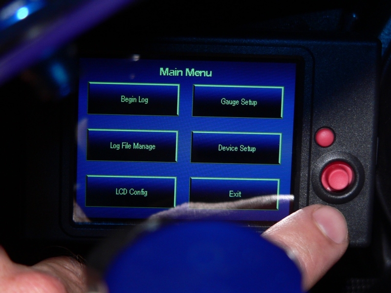
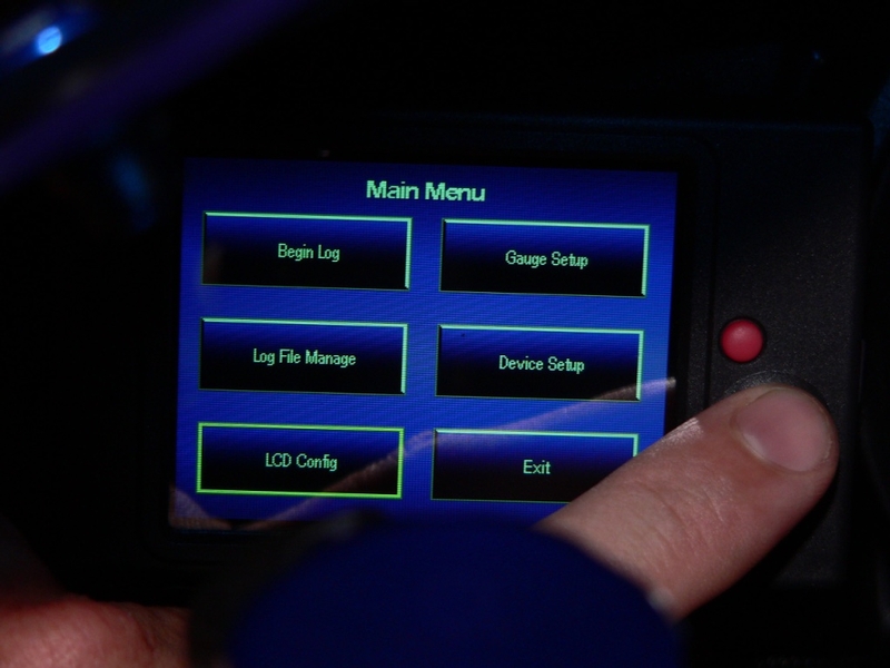
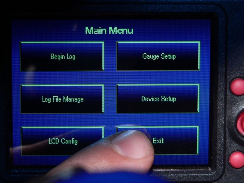
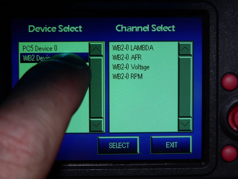
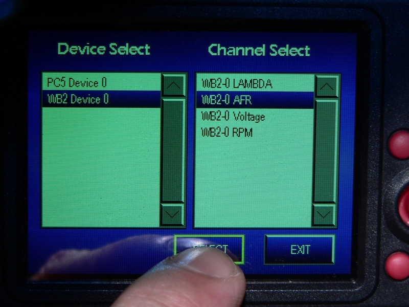
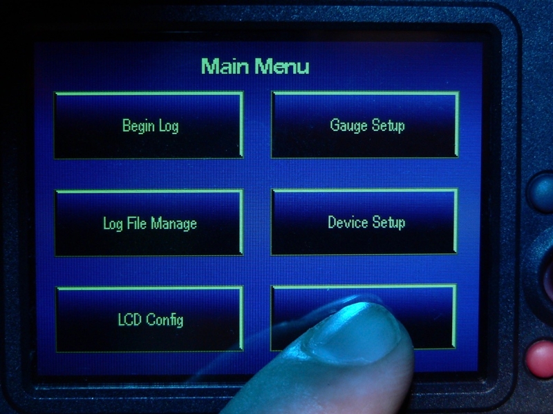
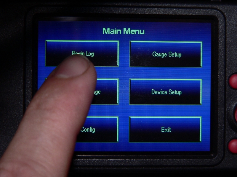
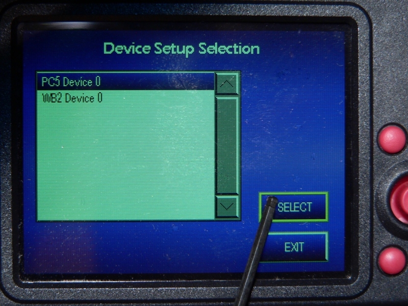
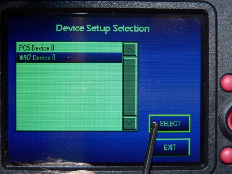
95. From the Main Menu, touch the Device Setup button to open the the Device Selection screen.

Select Wideband 2 Device 0 from the list of devices.

Touch Select.


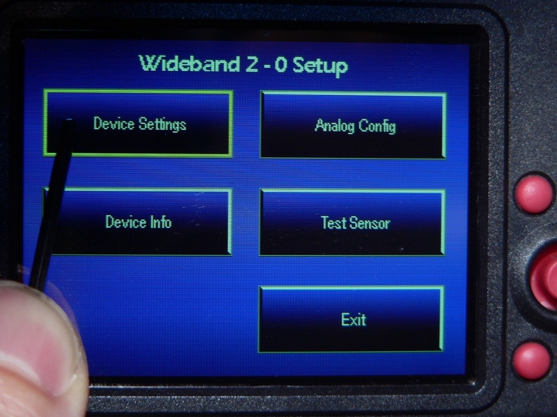
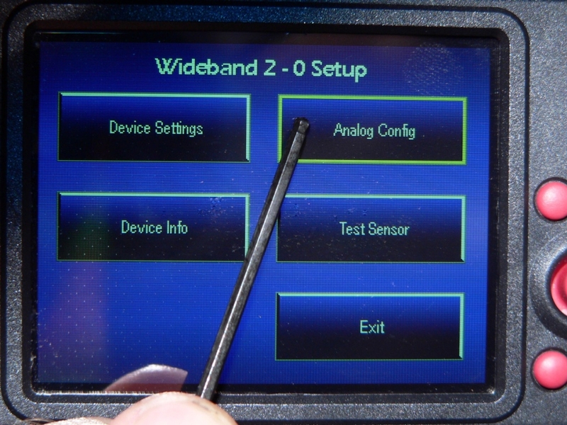
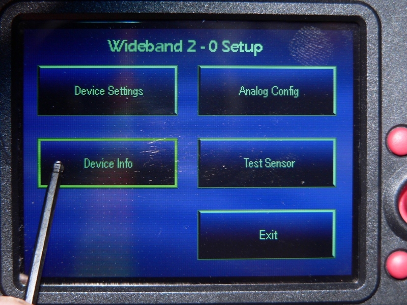
96. The Wideband 2 - 0 Setup screen opens.

Touch the Device Settings button.

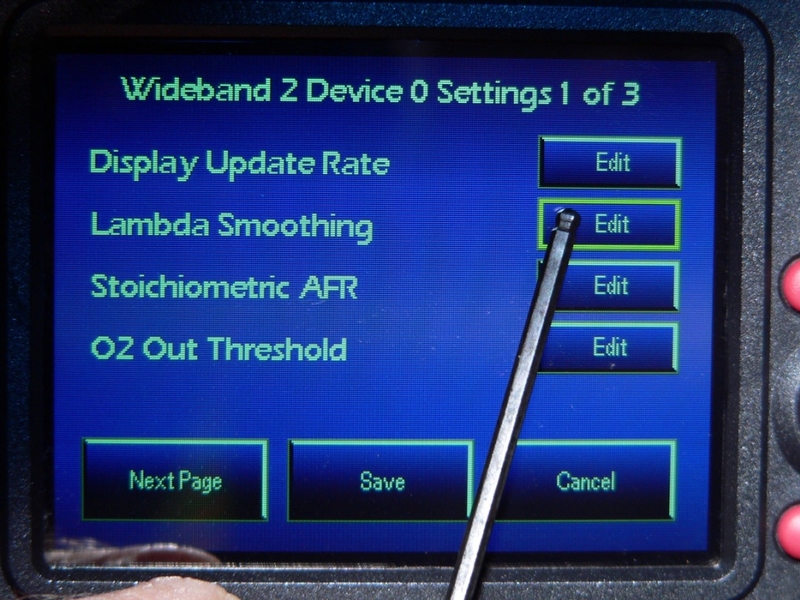
97. The Wideband 2 Device 0 Settings page 1 of 3 screen opens.

There are three pages (screens) of these settings. All settings alter the signal that is received by the LCD from the Wideband 2 or Autotune device. It will probably not be very beneficial or desirable to alter most of the default settings except for advanced tuning practices. Below is a brief description of each setting. You will note many of the settings are for Wideband 2 only. Wideband 2 is equipped with wiring to tap into the tachometer and analog channels. Since Autotune and Wideband 2 have the same type of O2 sensor, both units can be adjusted for the first three settings which effect AFR signal input.

WIDEBAND 2 DEVICE SETTINGS PAGE 1

Display Update Rate
Wideband 2 and AutoTune

Setting Range: 1-20
Default Value: 20
This is how frequently the gauges on the LCD update the most current figures from the previous ones. 1 is the slowest rate. This setting effects all channels of the WB2 or AT-200 device. It may be helpful to view some data on the LCD at a slower rate if the data changes too quickly to read accurately in real time.
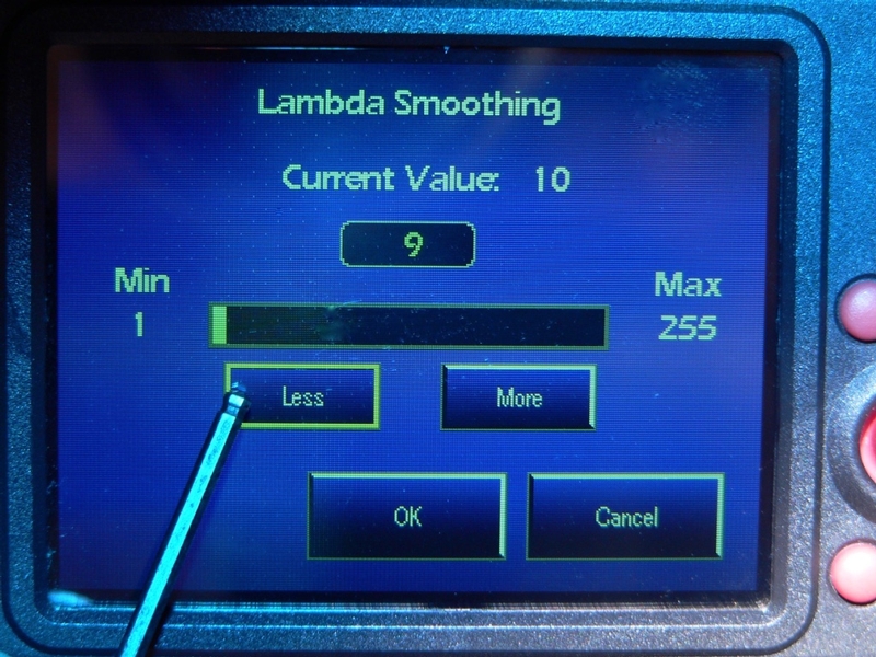
Lambda Smoothing
for Wideband 2 and AutoTune

Setting Range: 1-255
Default Value: 10

This setting averages the AFR pulses so that the readings will be more steady and easy to read in real time. This setting effects Lambda readings in the same way. The lower settings will provide the most detailed information with least latency which is best for data logging. Higher settings will cause changes in Lambda and AFR readings to be less jumpy which may be more desirable for viewing in real time.

Stoichiometric AFR
for Wideband 2 and AutoTune

Setting Range: 0-ambient
Default Value: 14.7

The stoichiometric AFR should be changed when using Lambda to tune for fuels other than ordinary gasoline. Stoichiometric AFR is achieved when the exact number of units of air are mixed with one unit of fuel so that complete combustion of fuel and oxygen occurs. No excess fuel or oxygen is left behind after combustion. The stoichiometric AFR for gasoline is 14.7 which is the default setting. You may contact Dynojet for stoichiometric AFRs of other fuels.

O2 Out Threshold
for Wideband 2 only

Setting Range: .9-1.1
Default Value: 1

For using Lambda to tune. Sets the voltage at which the narrow band signal (rich) and wide band signal (lean) occurs. This setting is only for Wideband 2.

The only settings I would consider changing as a beginner would be Lambda Smoothing and perhaps Display Update rate.

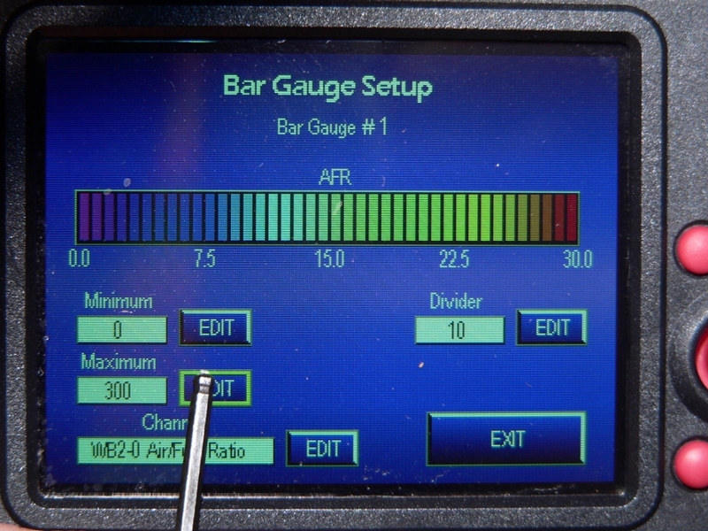
Touch the EDIT button after the feature you wish to change the setting of.


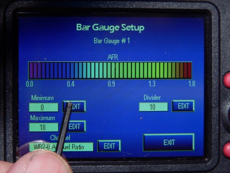
98. The feature’s screen opens displaying the current value and the set value.

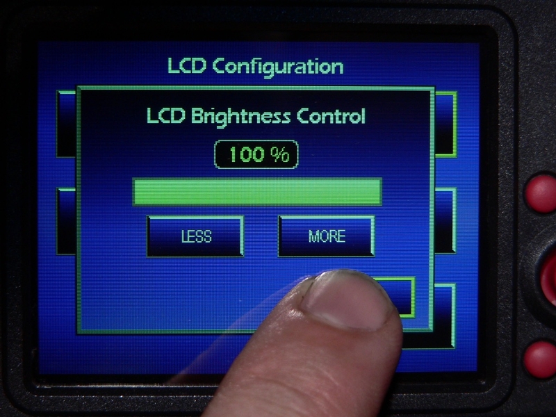
Touch the More button to increase the set value or touch the Less button to decrease the set value.


99. Touch OK to accept the set value and return to the Wideband 2 Device 0 Settings screen.
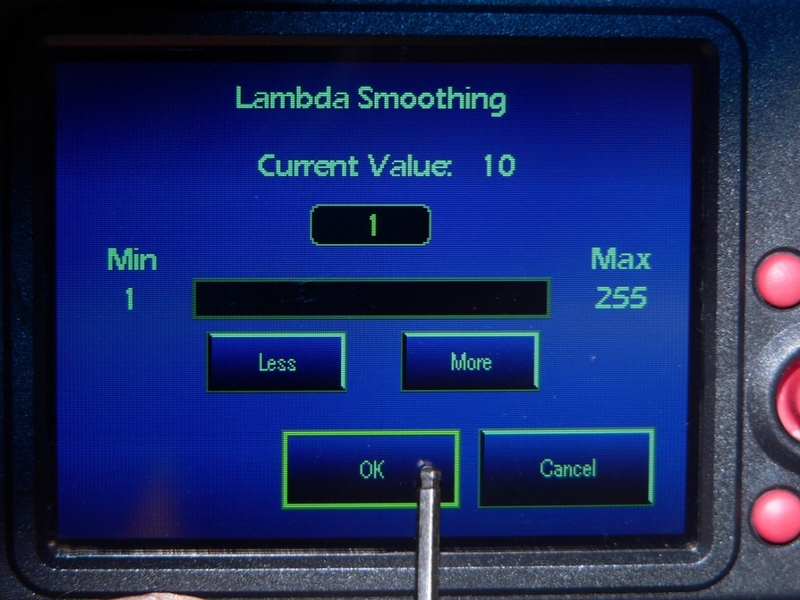
OR

Touch Cancel to retain the current value and return to the Wideband 2 Device 0 Settings screen.

100. From the Wideband 2 Device 0 Settings 1 of 3 screen,

Touch EDIT for the next setting you wish to change the value of and repeat steps 96 through 98.

OR

Touch Save to save the new setting and return to the Wideband 2 - 0 Setup screen.

OR

Touch Cancel to preserve the current values of all features and return to the Wideband 2 - 0 Setup screen.

OR

Touch the Next Page button to advance to page 2 of Wideband 2 Device 0 Settings.


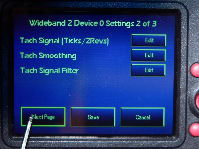
WIDEBAND 2 DEVICE SETTINGS PAGE 2

Tach Signal (Ticks / 2Revs)
for Wideband 2 only

Setting Range: 1-16
Default Value: 1

This changes the multiplier the Wideband 2 uses to interpret the tachometer signal. The multiplier will need to be adjusted to turn the signal into an accurate tachometer reading. I have noticed that Autotune’s tachometer signal only goes to 3000 rpm and the multiplier may be the cause of this. Unfortunately, AutoTune’s tach signal cannot be adjusted but the PCV’s rpm channel works very well.

Tach Smoothing
for Wideband 2 only

Setting Range: 1-16
Default Value: 2

Averages the tachometer signal from the Wideband 2 so that the rpm displays a smooth transition in level on the gauge.

Tach Signal Filter
for Wideband 2 only

Setting Range: 1-255
Default Value: 30

Filters out incorrect rpm inputs. It its possible for AutoTune and Wideband 2 to perceive very incorrect rpm. Though this event usually only happens for one or two tenths of a second, it can effect fuel trims.


101. Adjust any of the Wideband 2 settings on page 2 of Wideband 2 Device 0 Settings. Follow the procedures outlined in steps 97 through 99.

Touch the Next Page button to advance to page 3 of Widebandband 2 Device 0 Settings.

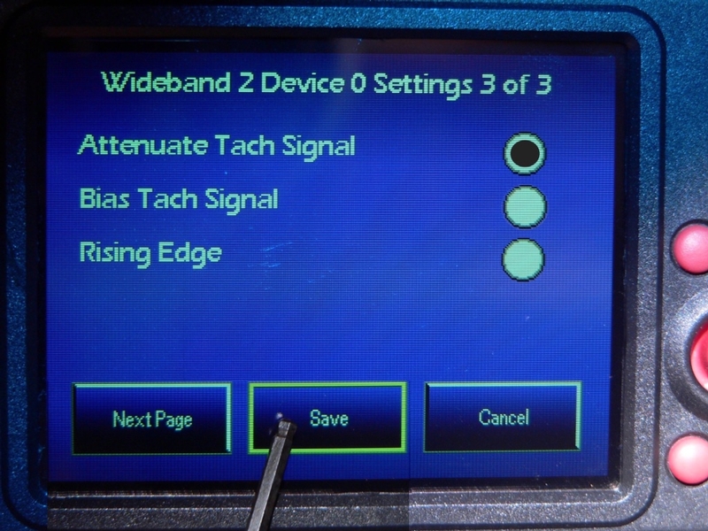
102. The features on page 3 of Widebandband 2 Device 0 Settings may be either turned ON or turned OFF by selecting or deselecting the bullet point for each. The Bias Tach Signal feature can only be selected when Attenuate Tach Signal has been turned ON.

WIDEBAND 2 DEVICE SETTINGS PAGE 3

Attenuate Tach Signal
for Wideband 2 only

Setting Range: Active or Inactive
Default Value: Inactive

Reduces the tachometer signal voltage from the Wideband 2 overall to filter out noise.

Bias Tach Signal
for Wideband 2 only

Setting Range: Active or Inactive
Default Value: Inactive

Biases the tach signal to a higher voltage.

Rising Edge
for Wideband 2 only

Setting Range: Active or Inactive
Default Value: Inactive

Allows the Wideband 2 to measure the rising edge on the RPM voltage signal.

Touch Save to save edits on all three pages of Wideband 2 Device 0 Settings and return to the Wideband 2 - 0 Setup screen.

OR

Touch Cancel to preserve the current values of all features on all three pages and return to the Wideband 2 - 0 Setup screen.

OR

Touch the Next Page button to return to page 1 of the Wideband 2 Device 0 Settings screen.


Wideband 2 / AutoTune Functions
- Analog Channel Input Configuration

103. From the Wideband 2 - 0 Setup screen, touch the Analog Config button.


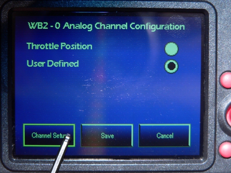
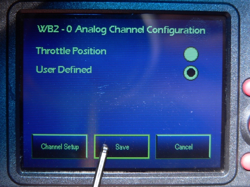
104. The WB2 - 0 Analog Channel Configuration screen opens.

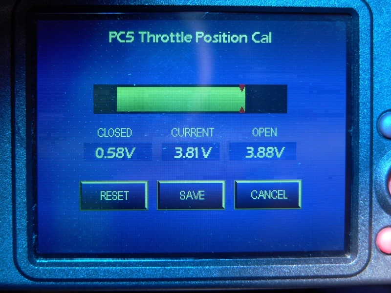
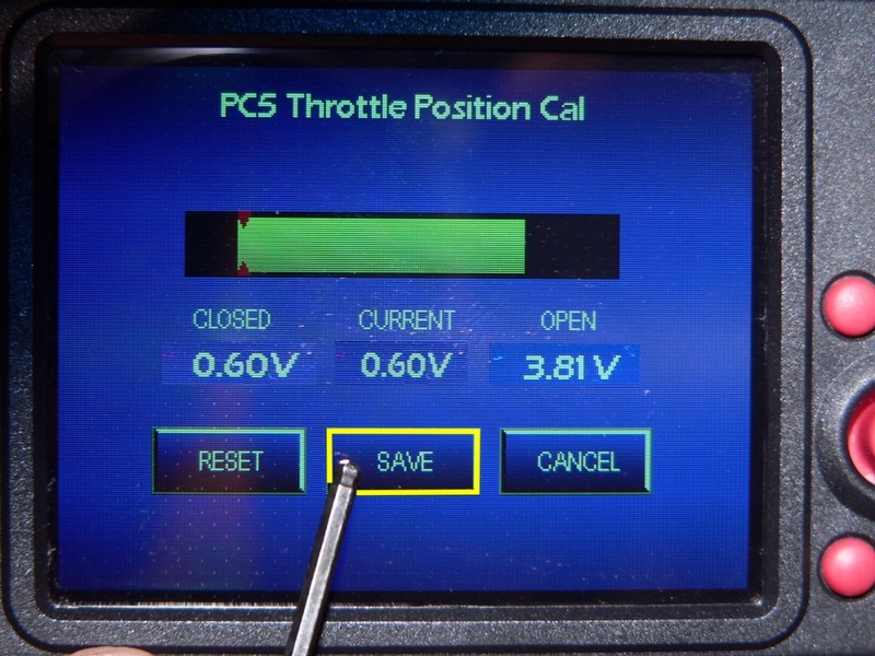
Select the bullet point for Throttle Position to enable throttle position calibration through the WB2/AT device.

Touch the Calibrate Throttle button to open the Throttle Calibration screen.

This function is identical to throttle calibration through the PCV. See steps 77 through 79 of PCV Functions to calibrate throttle position through the WB2/AT device.

Select User Defined to disable throttle position calibration through the WB2 and create a custom analog channel instead. In order to display on the gauges screen, the analog channel will require wiring to the WB2 device from a 1-5 V source such as the oil temperature sensor or the air box temperature sensor. Autotune modules are not equipped with the wiring for analog channel input. The User Defined selection will only work with Wideband 2.

Touch Save to save the selection and return to the Wideband 2 - 0 Setup screen.

Touch Cancel to return to the Wideband 2 - 0 Setup screen without making changes.

Touch Channel Setup to proceed and open the Wideband 2 Device 0 Analog Channel screen.


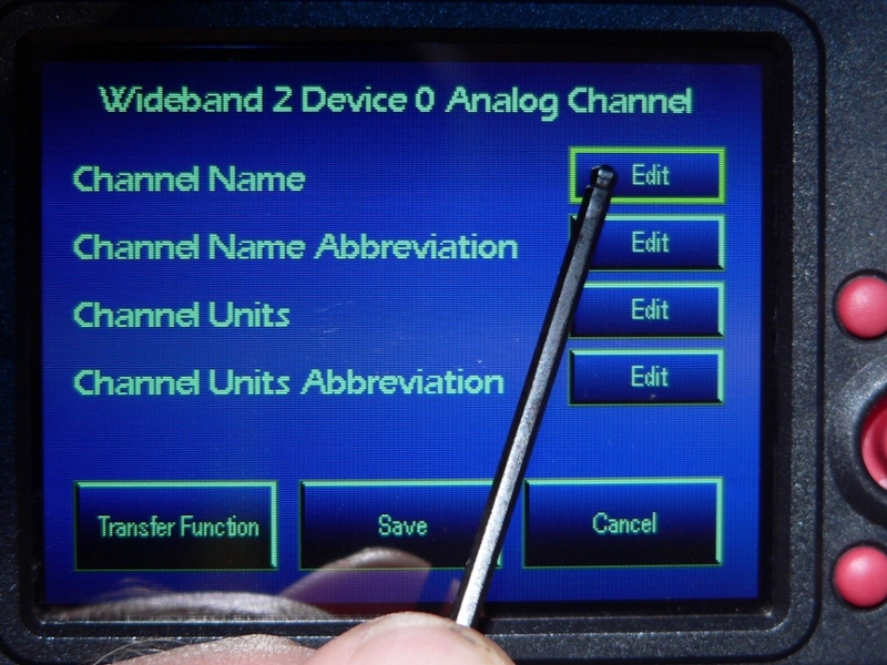
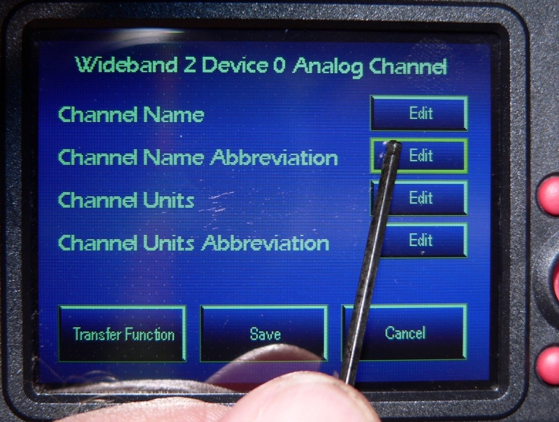
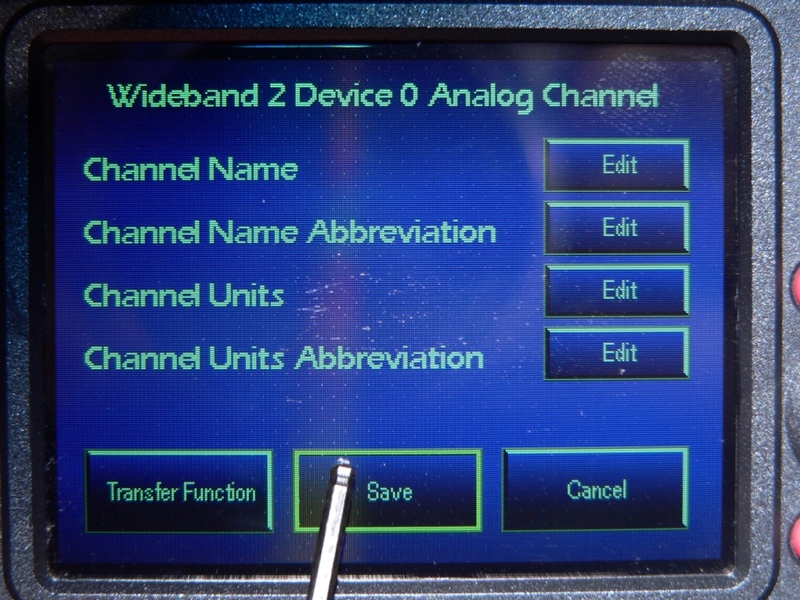
105. The Wideband 2 Device 0 Analog Channel screen opens.

Touch EDIT for Channel Name.


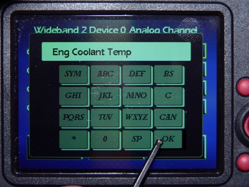
106. Use the alphanumeric keypad that opens to type the name of your custom channel. There is a limit of 20 characters. You may type lowercase letters and numerals by touching a key rapidly in succession or choose from several symbols by touching the * key. The name you type will appear in the menu of channel selections for the Wideband 2 device.

Touch the OK button.


107. The alphanumeric keypad will disappear.

Touch the EDIT button for Channel Name Abbreviation.


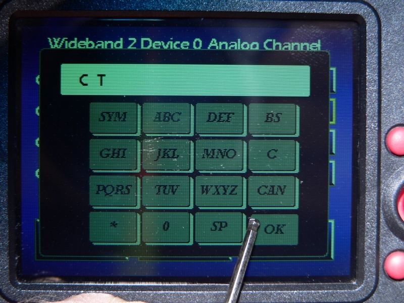
108. Use the alphanumeric keypad that opens to type the name abbreviation of your analog channel. There is a limit of 7 characters. This abbreviation will appear on the channel’s gauge in the Gauge Panel screen.

Touch the OK button.


109. The alphanumeric keypad will disappear.

Touch the EDIT button for Channel Units.

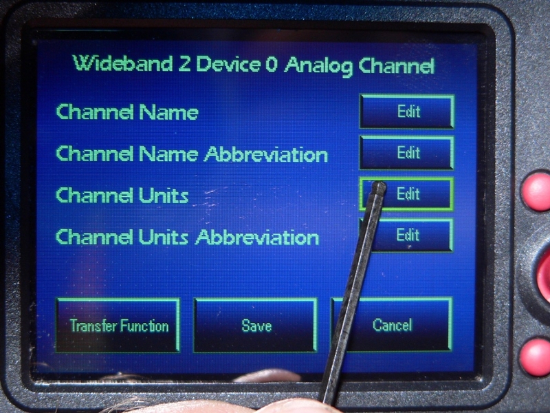
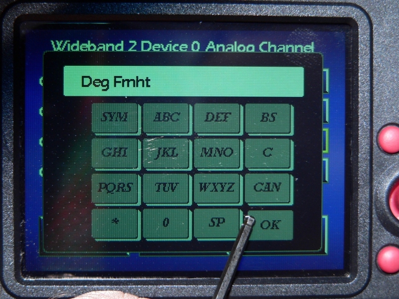
110. Use the alphanumeric keypad to type the name of the units that will be indicated on the analog channel’s gauge. There is a limit of 10 characters. This name will appear in the menu of channel selections for the Wideband 2 device.

Touch the OK button.


111. The alphanumeric keypad will disappear.

Touch the EDIT button for Channel Units Abbreviation.


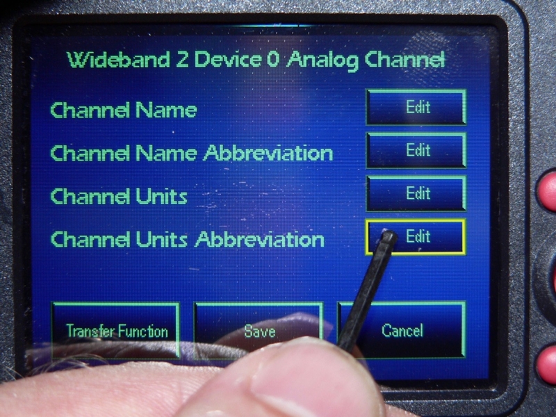
112. Use the alphanumeric keypad that opens to type the units abbreviation of your analog channel. This abbreviation will appear on the channel gauge in the gauges screen. There is a limit of 7 characters.

Touch the OK button.


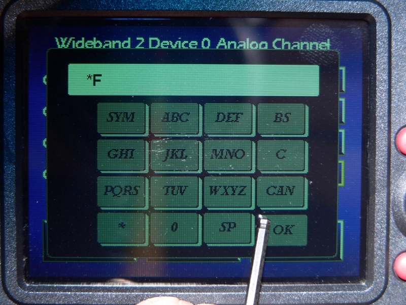
113. The alphanumeric keypad disappears.

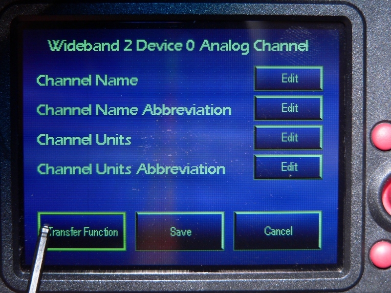
Touch the Save button to save the names and abbreviations entered for the analog channel and return to the WB2 - 0 Analog Channel Configuration screen.

OR

Touch the Cancel button to make no changes and return to the WB2 - 0 Analog Channel Configuration screen.

OR

Touch the Transfer Function button to proceed with setting up the analog channel.


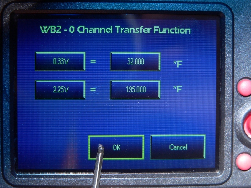
114. The Wideband 2 Channel Transfer Function screen opens.

You will either need to test the voltage of the analog channel or do some trial and error settings to calibrate the channel’s voltage to the scale of units you intend to use for the channel’s gauge.

I did some basic math to come up with the numbers I entered for the hypothetical analog channel I have created for demonstration. I have Autotune so the analog channel is not supported even if it is set up.

0° F************0v**************0% gauge reading

32° F************.33v**********0% gauge reading

141° F*********1.5v************50% gauge reading

195.5° F*******2.25v***********75% gauge reading

250° F*********3v**************100% gauge reading

Assuming the coolant has a 0-3 volt sensor with 0v being transmitted at 32 degrees Fahrenheit and colder, a max gauge reading of 250° F would display when the max 3v was transmitted.

The lowest reading on the gauge scale will be 32 F at .33v.

The highest reading on the gauge scale will be 250° F at 3v.

With a voltmeter on the coolant temp sensor and a thermometer taped to the radiator, I could determine what voltage was transmitted at a low temp point and a high temp point. I guess I probably would not try to get the coolant temp as hot as 195° F but this is just hypothetical. I could have used X voltage at 66° and Y voltage at 155° and that would have given the LCD enough info to calibrate meaningful numbers on the gauge display. When calibrating using two values, it’s usually best to shoot for the highest and lowest practical readings you can get.

Touch the button for the first voltage level.

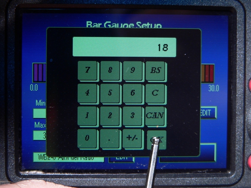
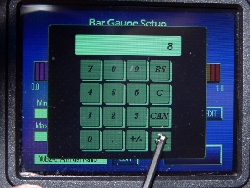
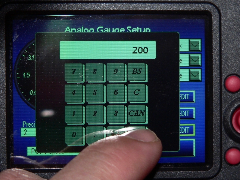
Use the numeric keypad to enter the a number for the first voltage level (no matter how you get it, by taking a logical guess or by measuring with a voltmeter).

Touch the button for the first gauge reading.

Use the numeric keypad to enter the number of units that correspond to the first voltage level.

Now do the same for a second voltage level which will correspond to a different gauge reading.

Touch the OK button to accept the voltages and units entered and return the Wideband 2 Device 0 Analog Channel screen.

OR

Touch Cancel to return the Wideband 2 Device 0 Analog Channel screen with no changes to the channel transfer function.


115. The Wideband 2 Device 0 Analog Channel screen opens.

Touch Save to save all entries for channel name, units, abbreviations, channel transfer calibrations and return to the WB2 - 0 Analog Channel Configuration screen.

OR

Touch Cancel to return to the WB2 - 0 Analog Channel Configuration screen with no changes to channel name, units and abbreviations.


116. The WB2 - 0 Analog Channel Configuration screen opens.

Touch Save to save the selected channel (analog or User Defined) and return to the Wideband 2 - 0 Setup screen.

OR

Touch Cancel to restore whatever channel had previously been selected and return to the Wideband 2 - 0 Setup screen.


117. Touch the Exit button on the Wideband 2 - 0 Setup screen to return to the Main Menu.

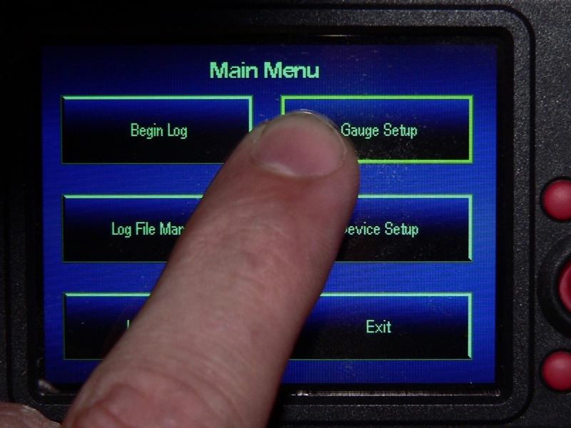
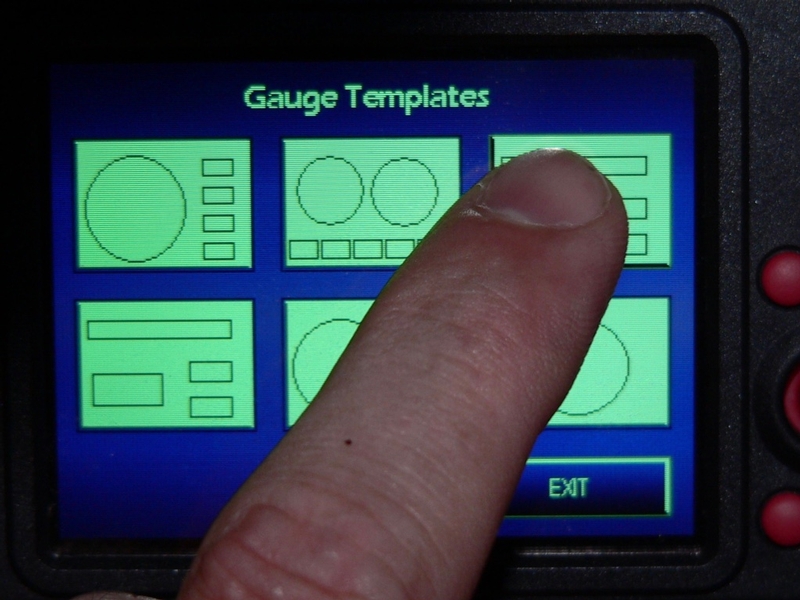
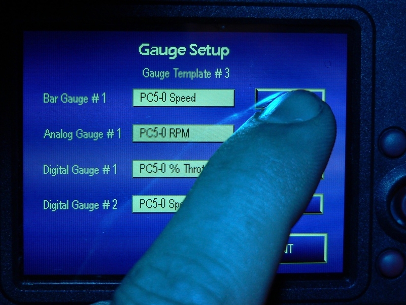
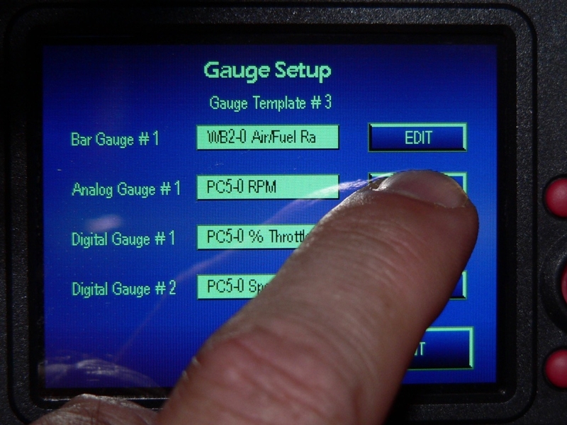
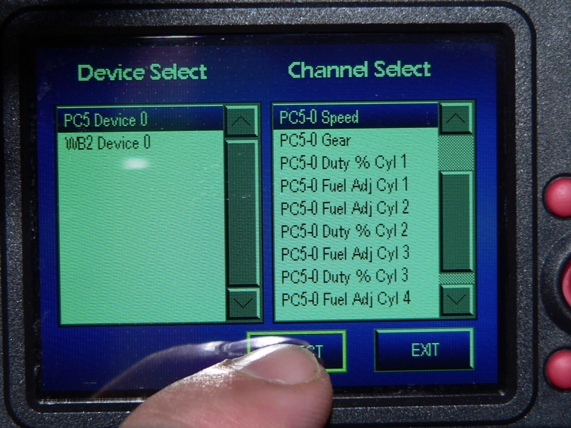
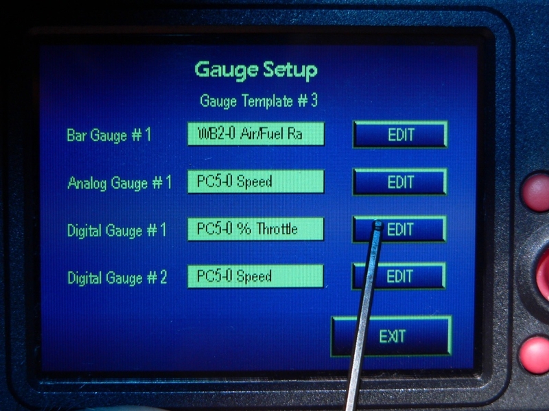
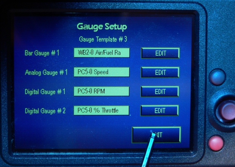
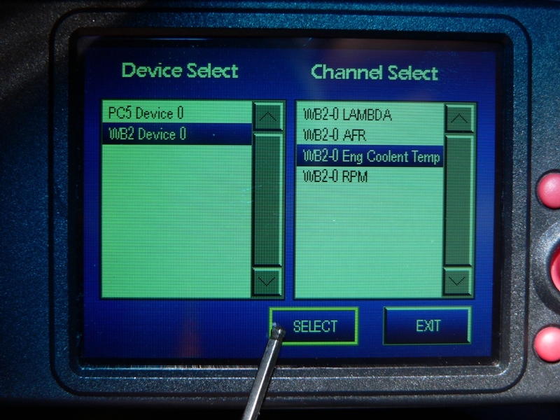
From the Main Menu, touch Gauge Setup > Gauge template > EDIT > Channel > WB2 Device 0

You will now see your analog channel listed in the Channel Select menu.

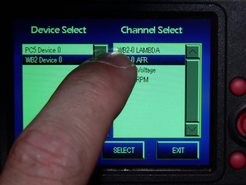
Select your analog channel form the Channel Select menu.

Touch the Select button.

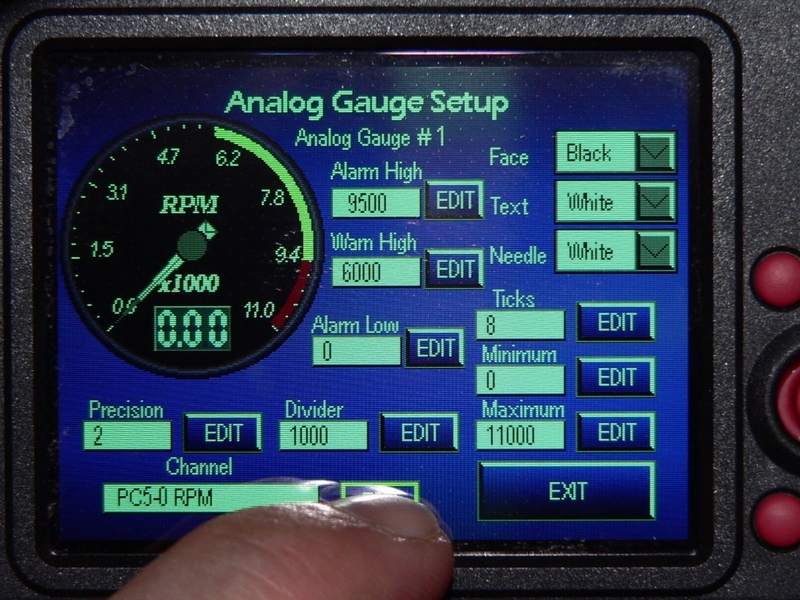
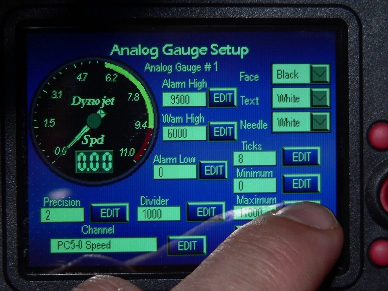
Refer to Gauge Setup, steps 19 through 54 to complete the procedures for setting up the gauge for your analog channel.

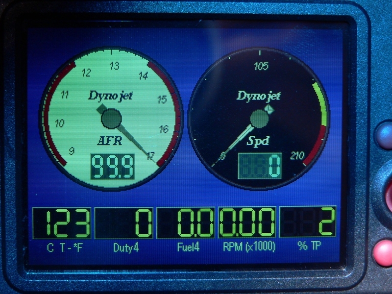
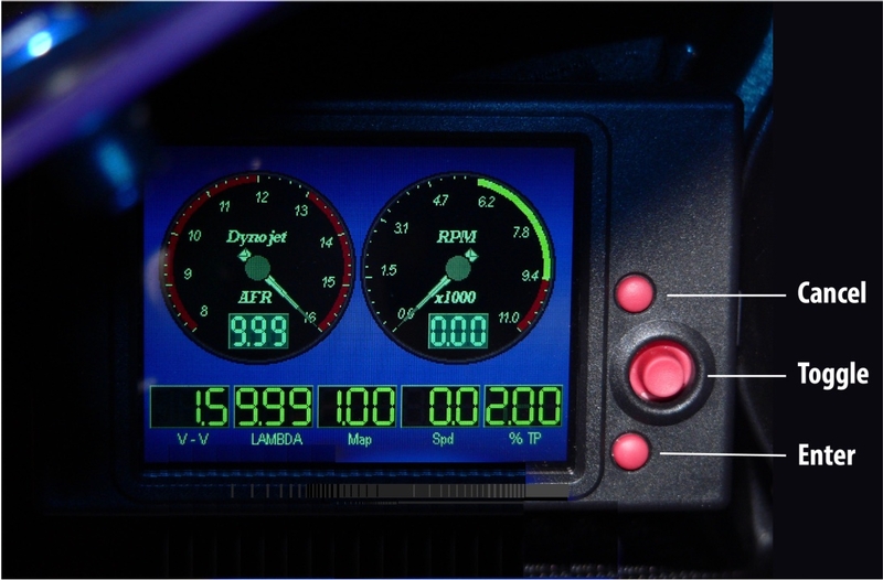
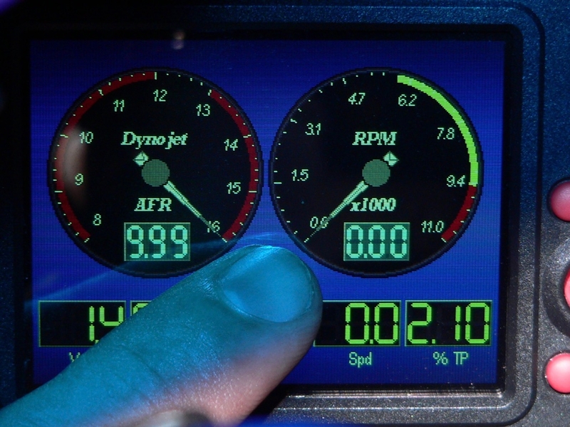
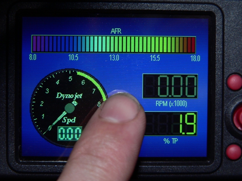
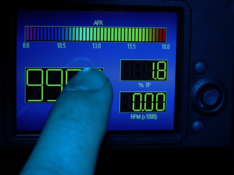
The abbreviation for my analog channel, C T appears with the abbreviation for it’s units, *F below digital gauge #5. It actually appears to be functioning accurately a short time after shutting the engine down. This is only a coincidence because I have no auxiliary wiring and Autotune which I have installed does not have an analogue input feature like Wideband 2.


Wideband 2 / AutoTune Functions
- WB2 / AT Device Information

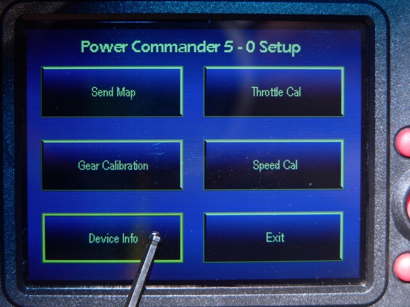
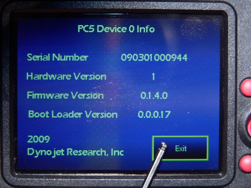
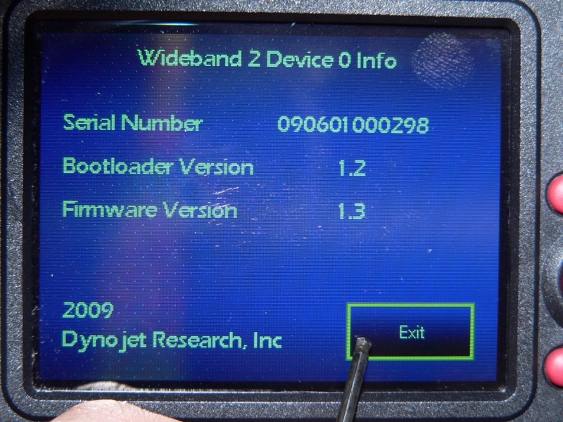
118. From the Main Menu, touch Device Setup > WB2 Device 0 > Select > Device Info


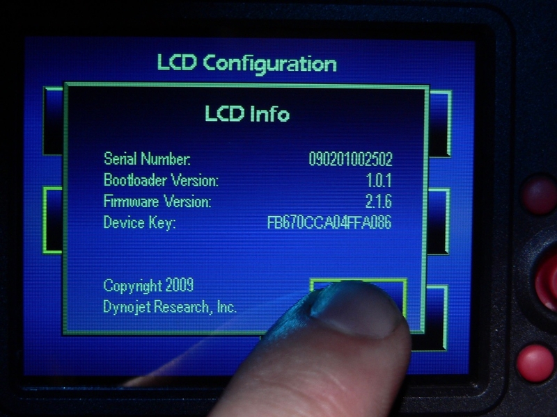
The WB2 Deice Info box opens showing firmware and serial number info for the WB2 /AT device in the network.

Touch the Exit button to return to the Wideband 2 -0 Setup screen.


Wideband 2 / AutoTune Functions
- O2 Sensor Test

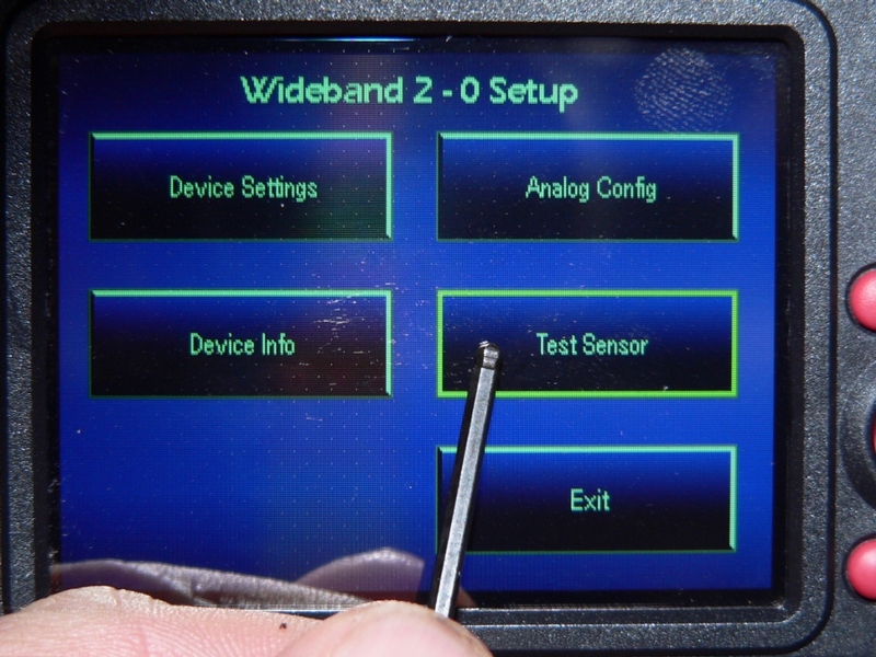
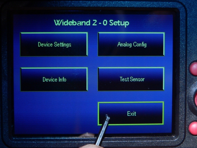
119. The Wideband 2 -0 Setup screen opens.

Touch the Test Sensor button.

Dynojet instructions say it is very important to remove the sensor and wave it in clean air to do the test. I have always tested with the O2 sensor while installed with the engine off and cold. The results seem to be consistent and reliable. You could have the WB2/AT module in view while testing with the LCD so that the test light on the module may be viewed but then you might as well use the O2 sensor test button on the module to conduct the test (see the concluding note in AutoTune Underseat Install).


120. The Wideband 2 - 0 Sensor Test screen will open.

Touch the Start Test button.


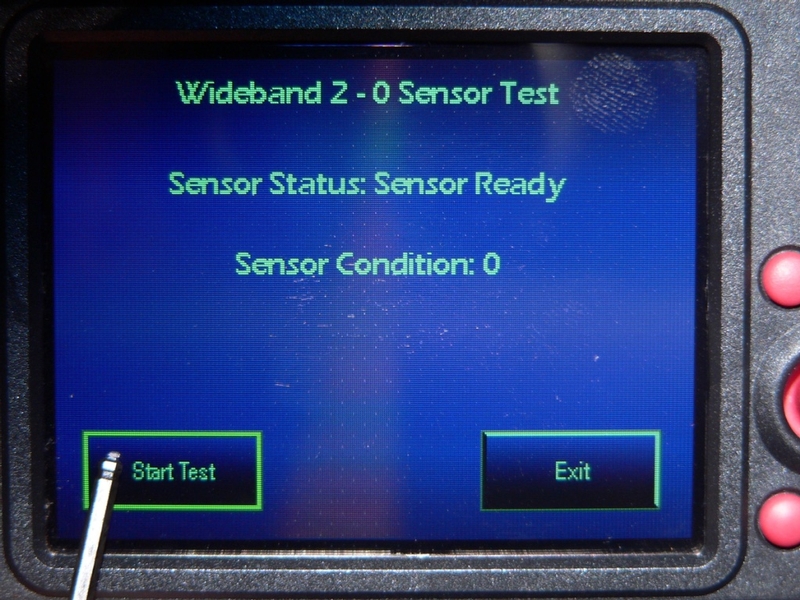
121. If you have the O2 sensor removed from the exhaust, wave it in the air while the test proceeds. It may take up to 20 seconds for a cold sensor to warm up enough to complete the test.

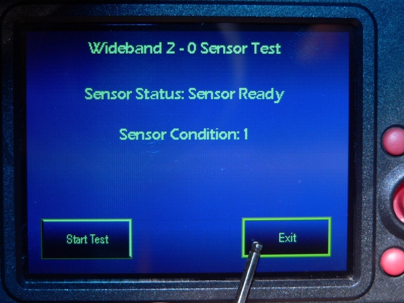
Read the test sensor number after Sensor Condition. You may also count the number of blinks registered on the test light of the WB2/AT device.

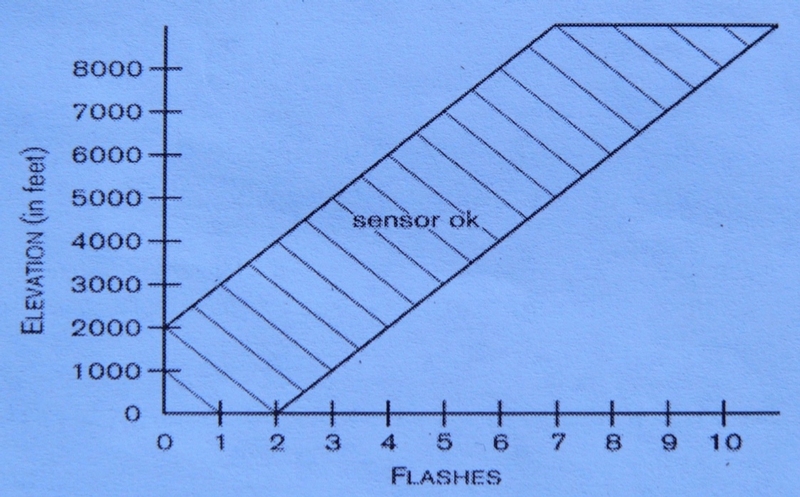
Refer to the chart below to compare your geological elevation to the number displayed on the LCD. If the sensor is out of range, the Sensor Condition displayed on the LCD will read XXX. The test light on the WB2/AT module will also blink repeatedly. If the sensor fails the test, replace it with a new one.

Touch the Exit button to return to the Wideband 2 - 0 Setup screen.


122. Touch Exit to return to the Main Menu.


* Last updated by: Rook on 1/26/2018 @ 5:53 AM *


'08 MIDNIGHT SAPPHIRE BLUE Now Deceased

Link | Top | Bottom

Rook


Rook's Gravatar

Joined: 03/28/09

Posts: 20574

RE: LCD-200 Setup and Functions
10/12/16 12:06 PM

ok all done.


* Last updated by: Rook on 10/15/2016 @ 11:23 AM *


'08 MIDNIGHT SAPPHIRE BLUE Now Deceased

Link | Top | Bottom

Rook


Rook's Gravatar

Joined: 03/28/09

Posts: 20574

RE: LCD-200 Setup and Functions
01/26/18 5:54 AM

All done again.


'08 MIDNIGHT SAPPHIRE BLUE Now Deceased

Link | Top | Bottom


Welcome to zx14ninjaform.com!
 
New Topic Reply
Next Page

Page: 1

Previous Page

New Post

Please login to post a response.