


Wheel Removal and Installation
Wheels are removed frequently so that tires may be changed or to remove sprockets or brake discs from the wheels. Outside of those, there is not much reason to take wheels off unless there is a problem with the wheel itself.
Front Wheel Removal
Tools:
6mm hex tool
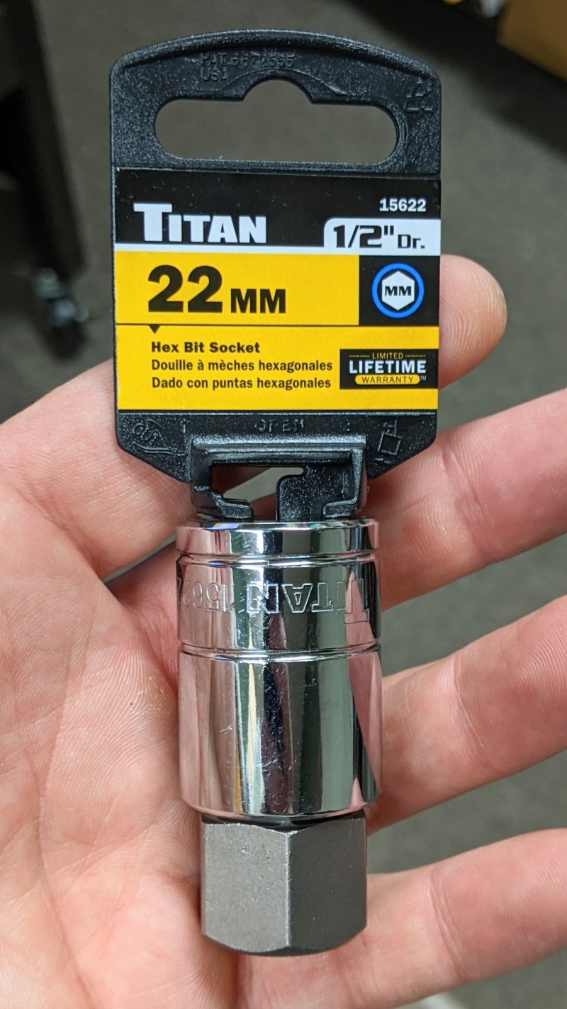
22mm hex axle nut wrench
13/16” spark plug socket
6” ratchet extension
front and rear stands
books or other flat objects
5mm hex tool
8mm socket
light wire or string
Sharpie permanent marker
high temperature grease
torque wrench
Do First:
Remove front brake calipers (see BRAKE CALIPER REMOVAL, steps 1 through 3)
Remove the front fender bolts (see Newbies’ Guide to Fairings Removal, Front Fender).
1. Using a 6mm hex tool, loosen the pinch bolts on the left fork bottom where the front axle nut is located.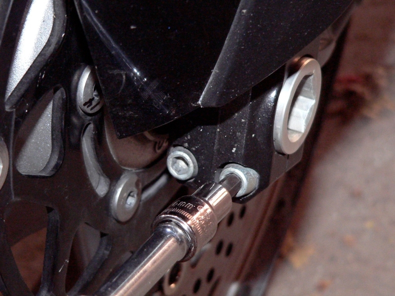
2. Use a 22mm hex axle nut wrench to loosen the front axle on the left fork bottom. Do not remove the axle nut.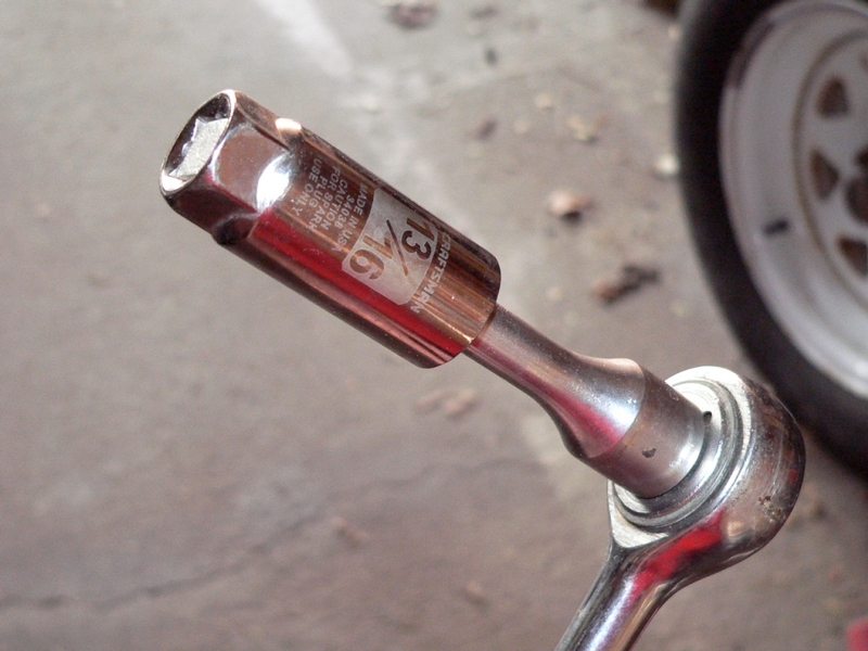
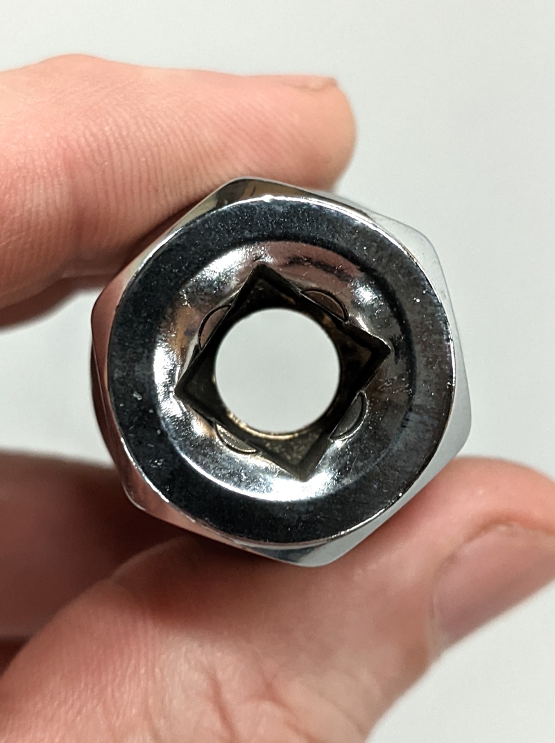
An excellent 22mm hex axle nut wrench can be improvised by removing the internal rubber boot from a 13/16” spark plug socket. Place the socket backward on a 6” extension and attach the extension to a ratchet.
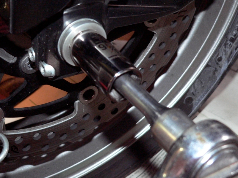
The hex will fit the axle nut perfectly.
3. Loosen the two pinch bolts at the bottom of the right fork with a 6mm hex tool. 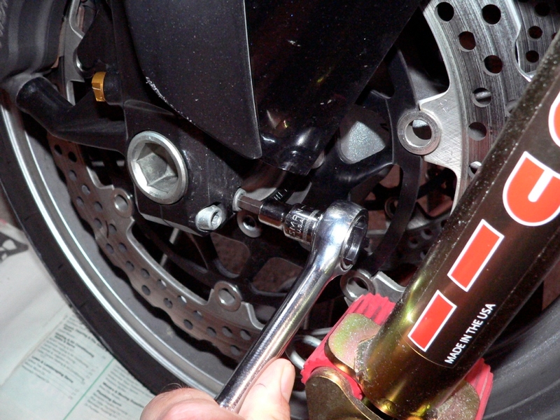
4. Lift the motorcycle onto a rear stand and front stand. Place books books or other flat objects under the front wheel so that all weight is removed from the front axle. 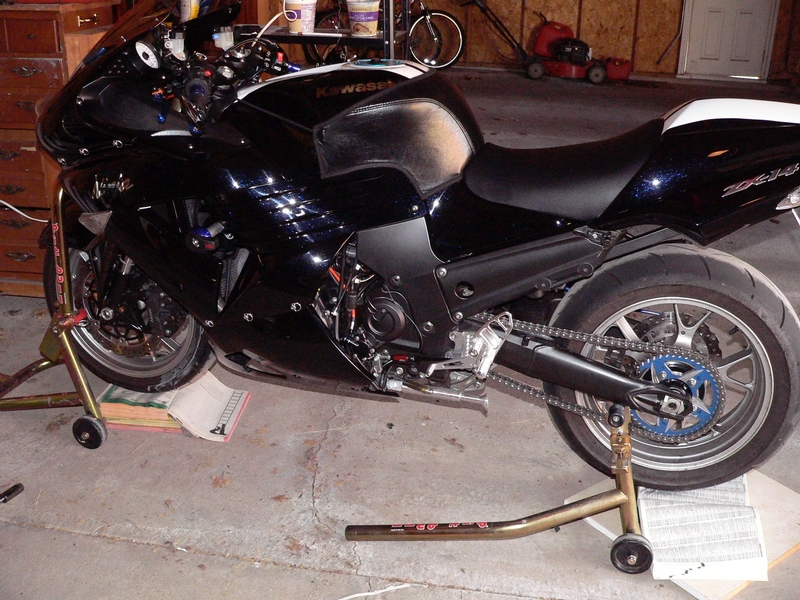
Large telephone books or department store catalogues make perfect supports for tire removal. They can be stacked and opened to the proper thickness to match the distance the tire is lifted from the floor.
5. Remove the front axle nut.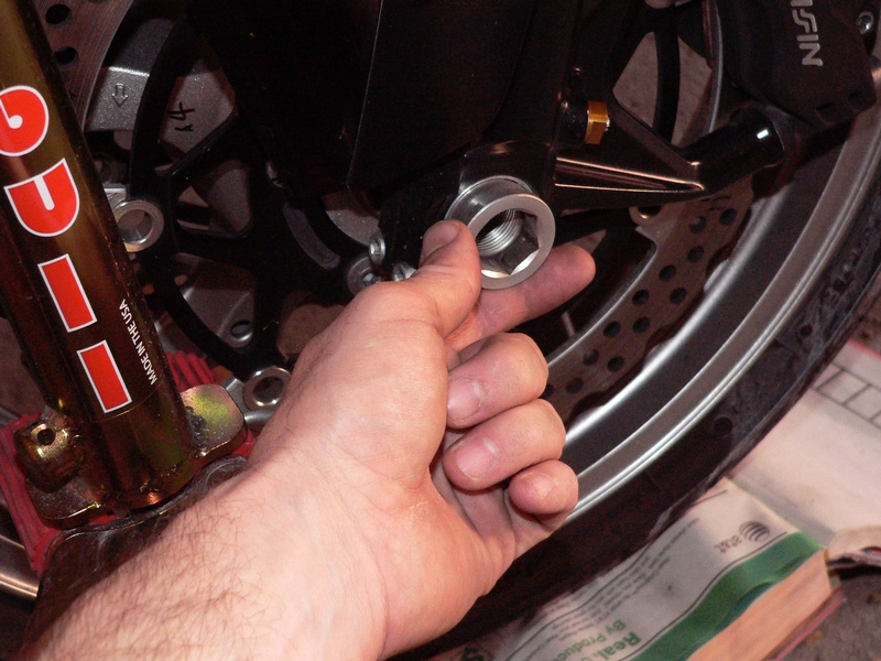
6. Pull the front axle out of the axle clamp on the right fork bottom. 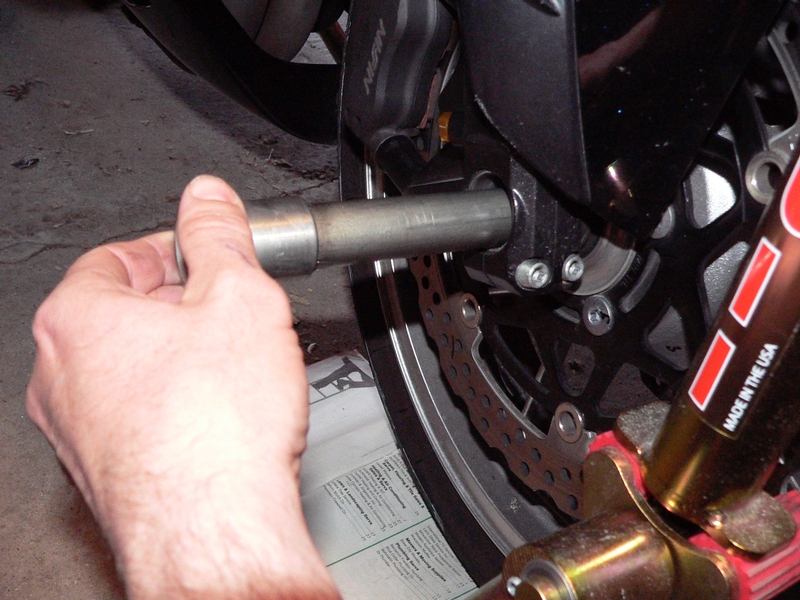
7. Lift the fender and roll the front wheel out from between the forks. The fender may be left hanging loose between the forks on the OEM brake lines. If aftermarket lines are on the bike, carefully pull the fender out from between the forks. Leave the objects that supported the front wheel exactly as they were placed. The support will be used to reinstall the front wheel to the forks at the proper height.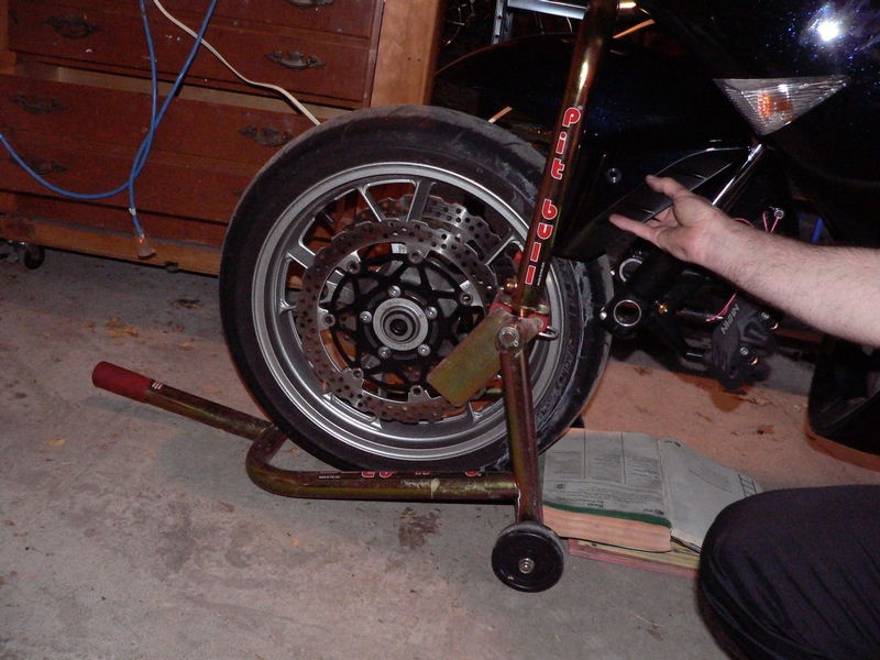
Take care in handling the front wheel after it is removed so that the brake rotors do not become warped or damaged.
8. Remove the spacer from each side of the front wheel hub.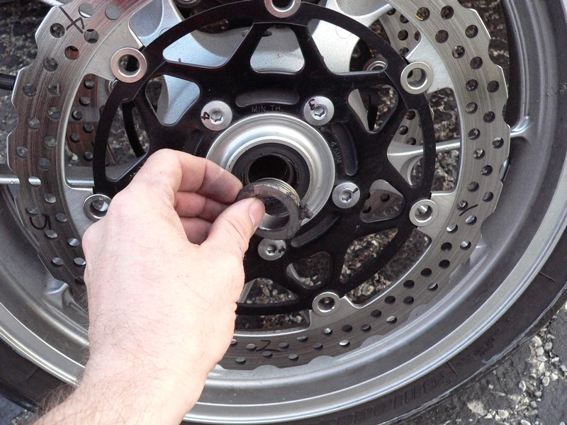
9. The front wheel spacers are identical on both sides but I mark them with a Sharpie to be placed back in the side they came from.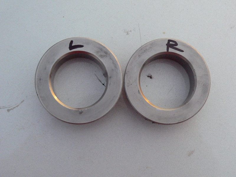
Front Wheel Installation
Check front wheel bearings for smooth turning. There should be no lateral play in the bearing and there should be no vertical slop. Check brake pad wear.
10. Apply high temperature grease to the rubber seal on each side of the front axle bearings.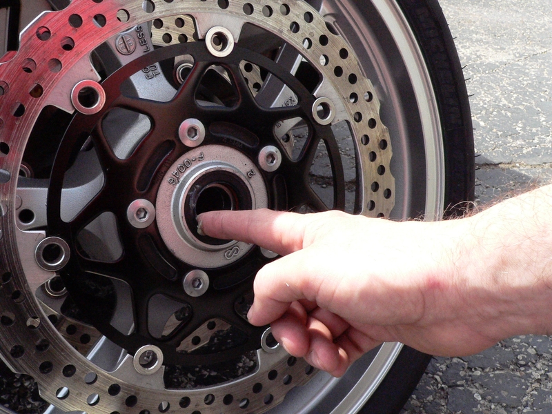
11. Install each front axle spacer to the front axle hub.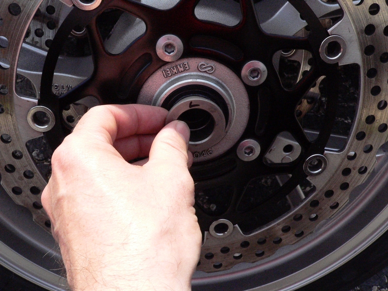
12. Roll the front wheel between the forks onto the objects that were piled under it before removal (step 5). Take care that the arrow on the wheel spoke points in the direction of forward rotation. 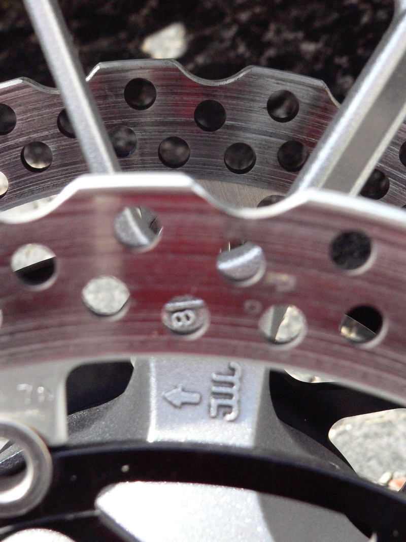
Position the front fender on top of the front tire. 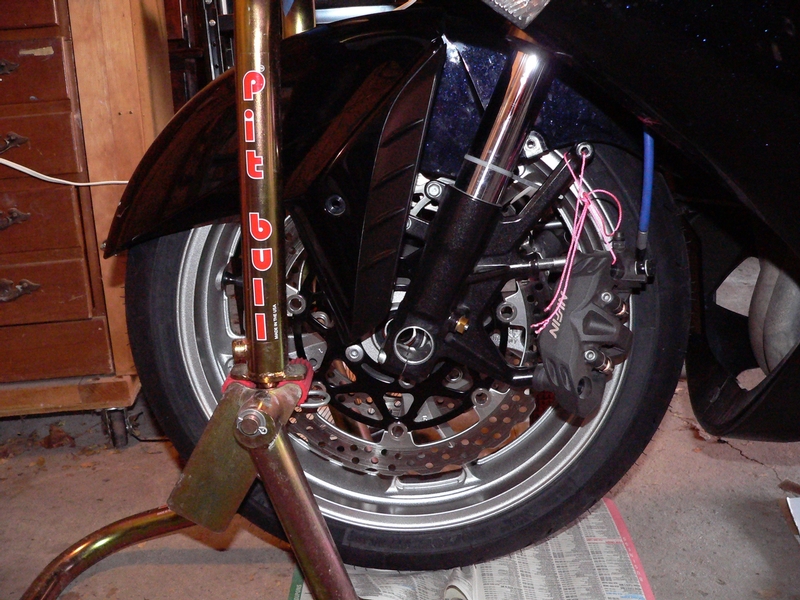
13. Press the spacers forward with thumbs while alining the wheel hub with the axle clamps using the index fingers. 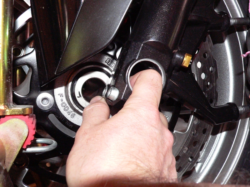
14. Apply high temperature grease to the front axle.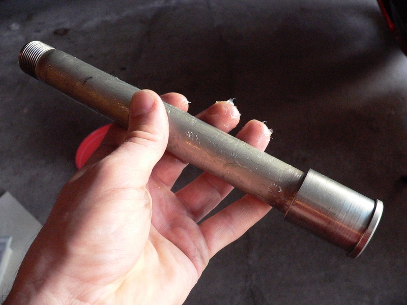
15. Push the front axle through the right fork clamp and smoothly through the front axle hub. Do not force the axle but adjust the front wheel as needed to provide proper alignment.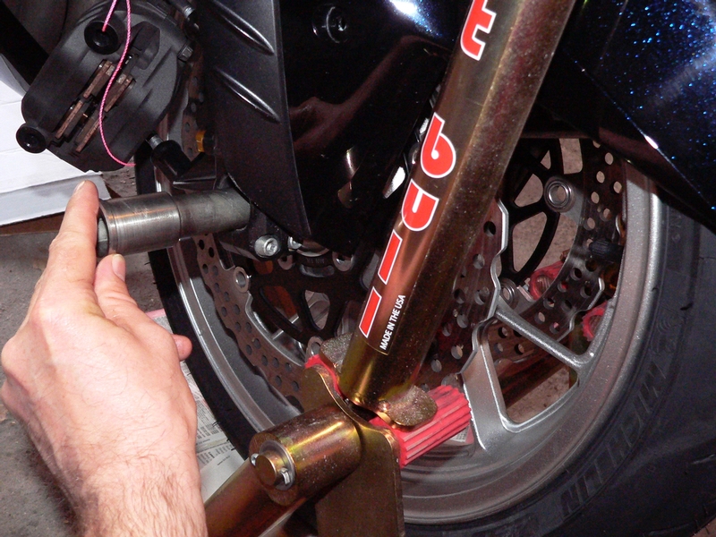
16. On the left fork, thread the front axle nut in snug so that the axle is pulled against the right axle clamp and the axle nut is pressed against the left axle clamp. 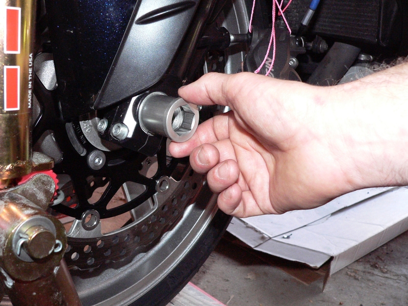
17. Remove the front stand. Bounce front suspension 4 to 5 times to seat the axle. 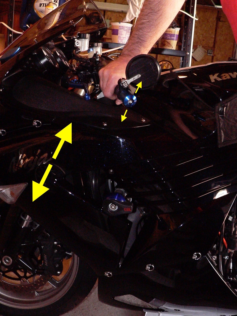
Torque the front axle nut to 93.7 foot lbs using a 22mm axle nut wrench. You may need to hold the axle with a wrench inserted in the right side so that the axle does not turn while the axle nut is torqued.
18. Tighten the right side pinch bolts first using a using a 6mm hex tool, then the left side. Draw the right pinch bolts up, switching from one to the other until the pinch bolts are evenly torqued to 15 foot lbs. 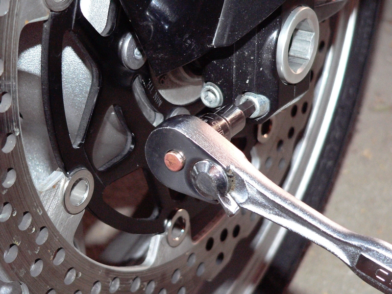
19. Torque the left pinch bolts in the same manner as the right.
Reinstall the calipers to their mounts (see CALIPER REMOVAL, steps 4 and 5).
Fasten the front fender to its mounts (see Newbies’ Guide to Fairings Removal, Front Fender).
Rear Wheel Removal
Tools:
6mm hex tool socket
pliers
32mm deepwell impact socket
30 inch breaker bar.
rear stand.
flat objects such as books
light gauge wire or string
Sharpie permanent marker
high temperature grease
rubber mallet
Torque wrench
new cotter pin
OEM arrangement of the rear axle is to have the axle nut on the left hand side. I switched the axle nut to the right side of the bike. This is because the axle is levered away from the adjuster screws when the axle nut is tightened on the left causing the
chain to be pulled tighter than it was adjusted. When placed on the right, the axle nut is levered against the adjuster screws when it is tightened.
20. Loosen rear brake caliper mounting bolts using a 6mm hex tool socket.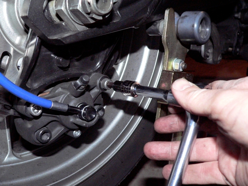
21. Remove the cotter pin from the rear axle castle nut using a pair of pliers (The pin in the picture is reusable). 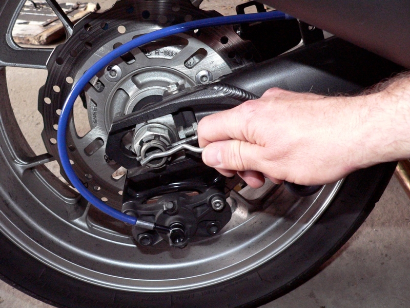
22. Loosen rear axle nut using a 32mm deepwell impact socket and a 30 inch breaker bar.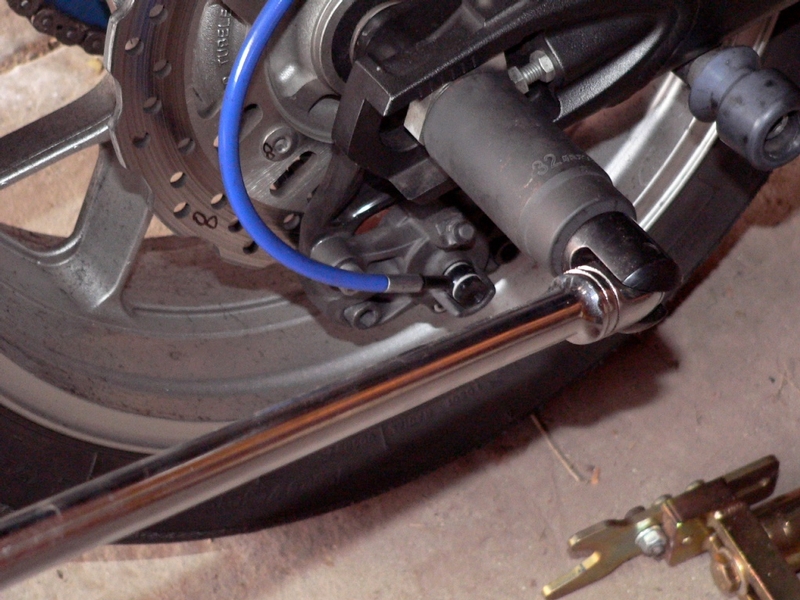
23. Lift the rear wheel off of the floor using a rear stand. Place flat objects such as books under the rear wheel so that all weight is removed from the rear axle.
Remove the rear break caliper (see BRAKE CALIPER REMOVAL, step 7).
24. Use a Sharpie permanent marker to mark a rear sprocket tooth so that it can be aligned to the same drive chain link when reinstalled.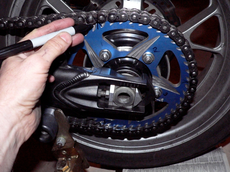
25. Remove the rear axle nut, washer and chain adjuster block. 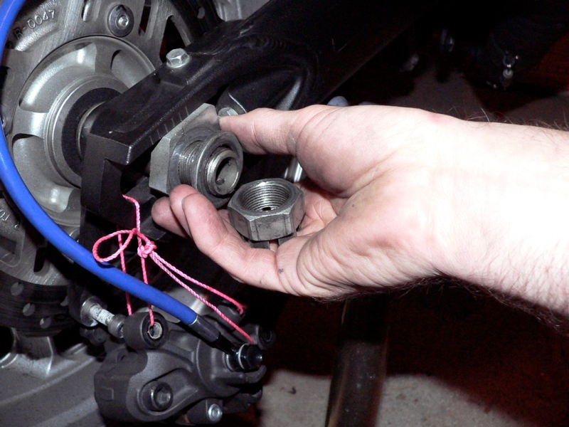
26. Pull the rear axle along with the other adjuster block from the swing arm.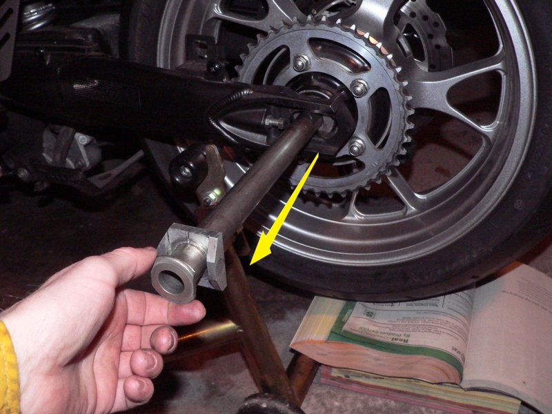
27. Slide the rear caliper mounting plate straight back and off of the spline on the inside of the right swing arm. Pull the rear brake mounting plate out from between the right wheel spacer and the inside of the axle slot. 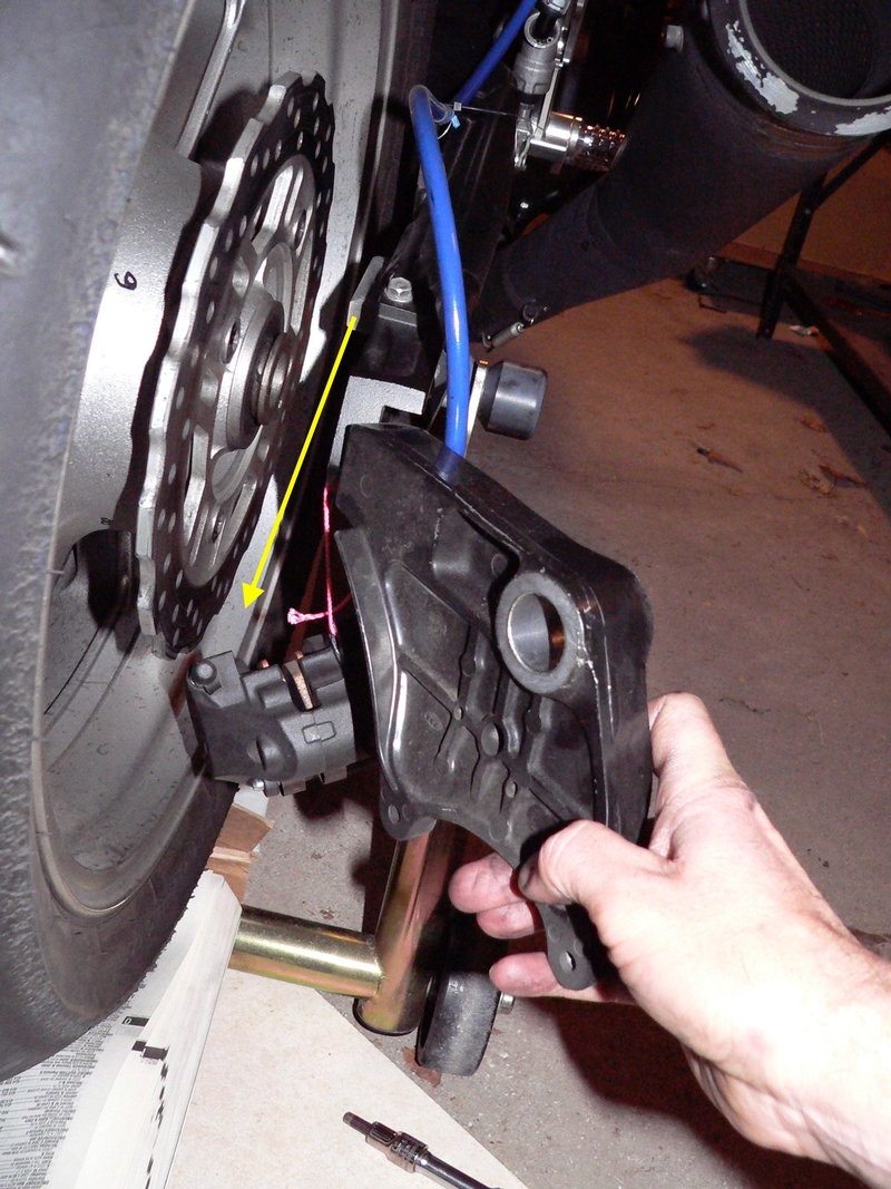
28. The adjuster block that the axle nut and washer tighten against is smooth on both sides. The other axle block has flats that fit with the flats on the non threaded end of the axle. 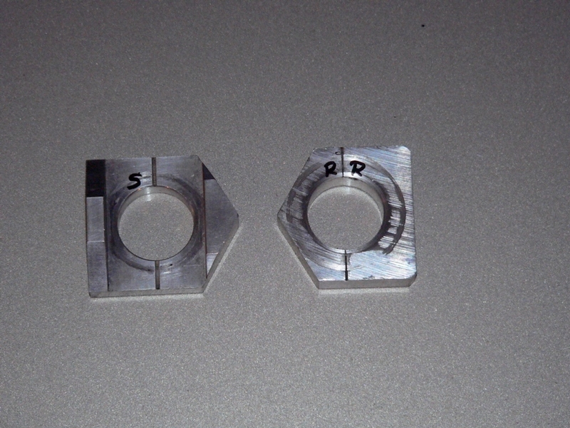
29. Push the axle all the way to the front of the axle slots. Lift the chain off of the rear sprocket and lay it over the end of the swing arm. Secure the chain to the axle slot with string or light wire.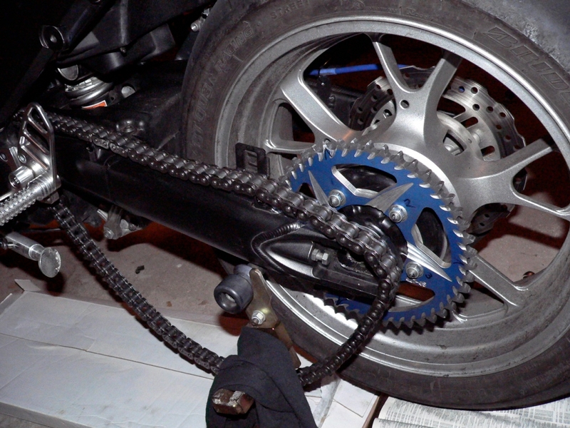
30. Roll the rear wheel out of the swing arm. Leave the objects that supported the rear wheel in place so that they may be used to align the axle, swing arm and rear wheel hub at the proper height when the rear wheel is reinstalled. 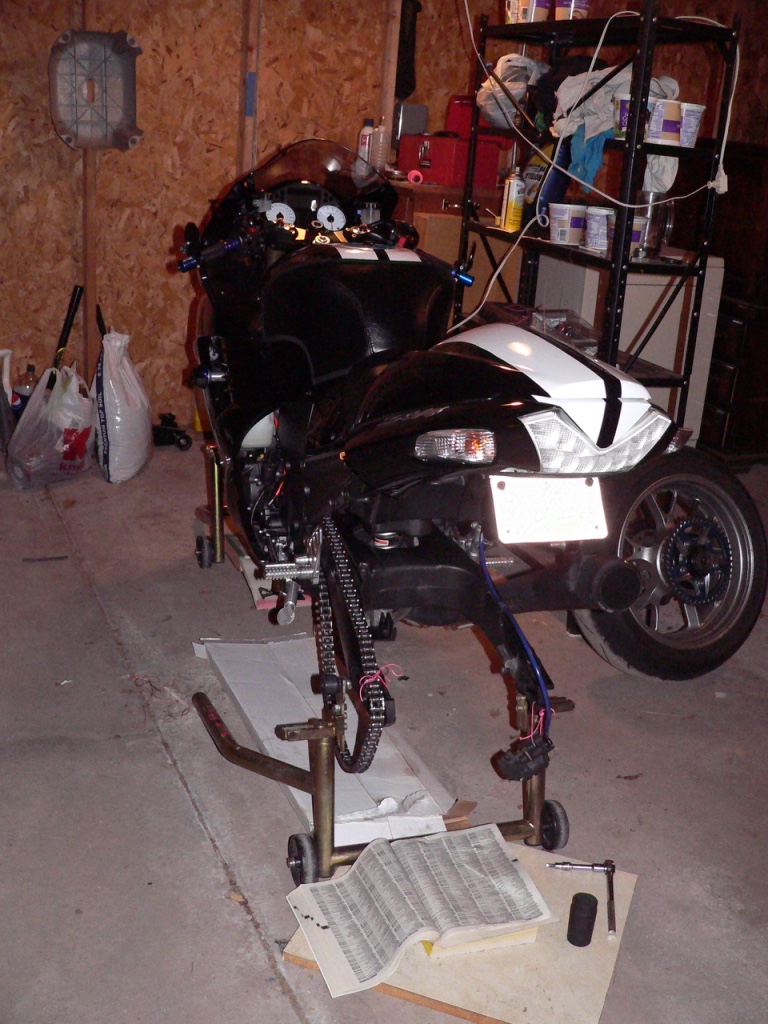
31. Remove the rear wheel spacers. The left spacer and the right are not identical and will only fit properly to the side of the hub that they are designed to mate with.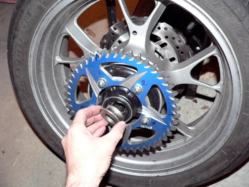
32. Mark each rear wheel spacer with a permanent marker for easy identification.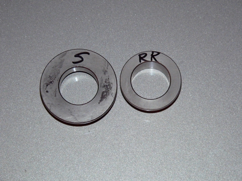
Rear Wheel Installation
33. Apply high temperature grease to the rubber grease seal lips. 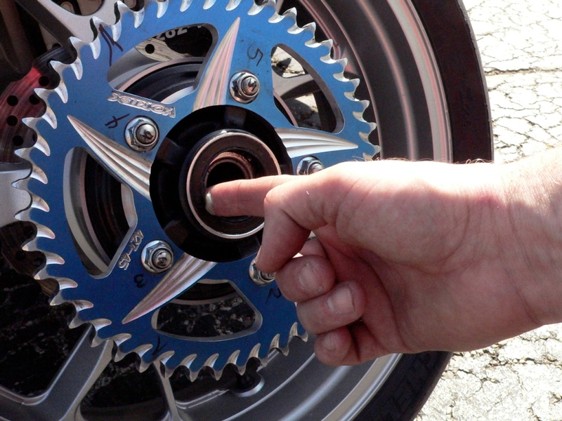
34. Install the rear wheel spacers to the proper sides of the rear wheel hub.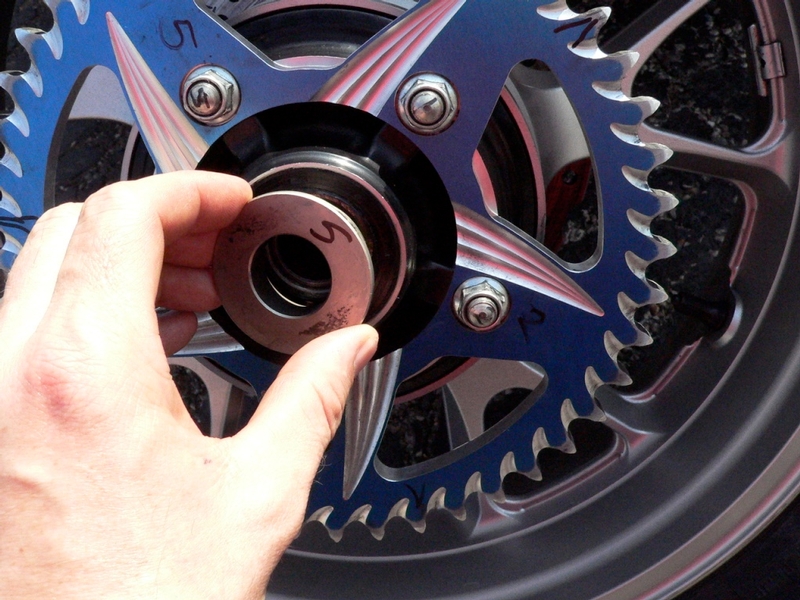
35. Roll the wheel into the swing arm atop the books that were placed under the wheel before it was removed. Push the wheel in until it touches the inside front of the swing arm.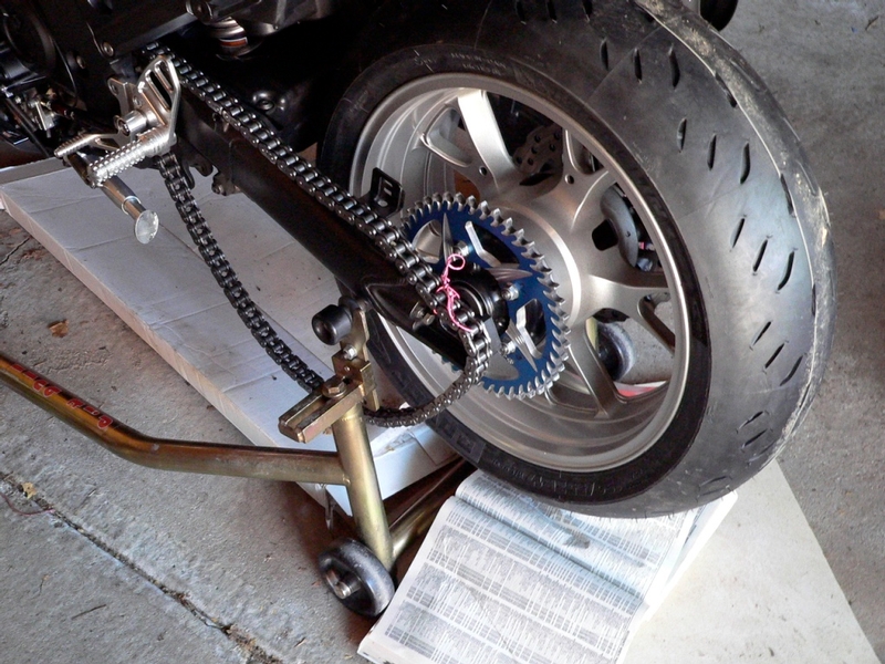
36. Untie the drive chain from the swing arm and place it onto the rear wheel sprocket so that the chain link that was marked in step 33 is matched to the tooth it was engaged with before the wheel was removed. 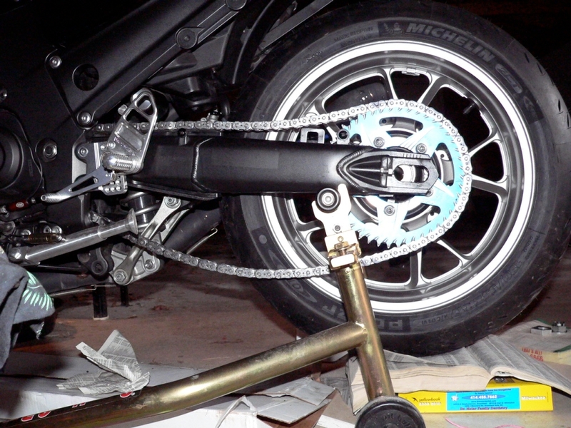
37. Slide the rear brake caliper mounting plate onto the spline inside of the right side of the swing arm. 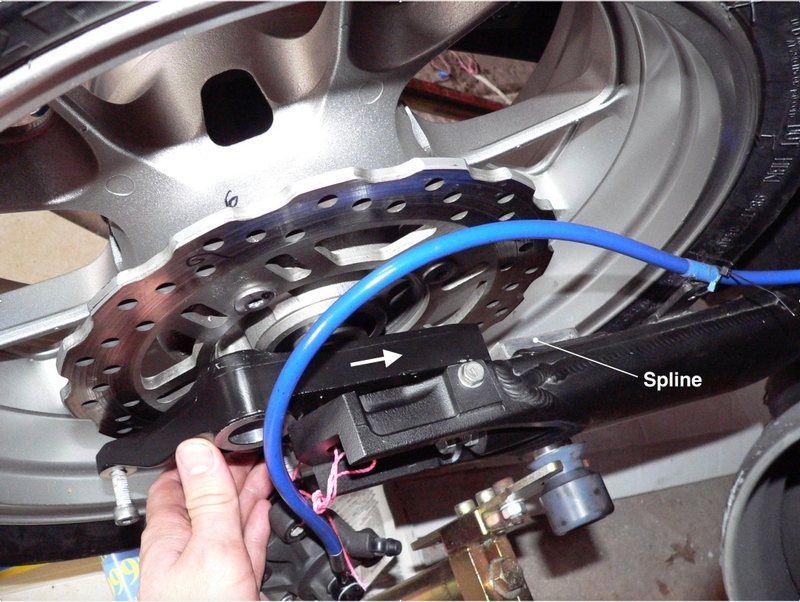
38. Place the axle block that matches to the flats on the end of the rear axle. Coat the rear axle with high temperature axle grease. 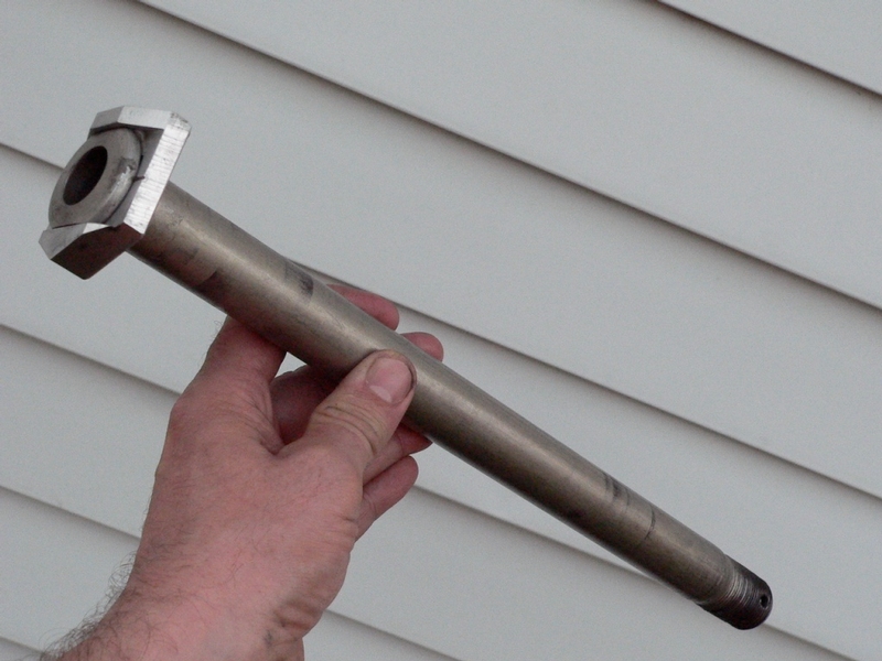
39. Pull the rear wheel back in the swingarm until the drive chain feels taught. Visually align the rear wheel hub with the axle slots and the hole in the rear brake mounting plate. Press the rear axle through the swing arm slot and carefully push it through the wheel hub. Do not force the axle. It will be necessary to wiggle and shift the parts so that they align and the axle will pass through without binding.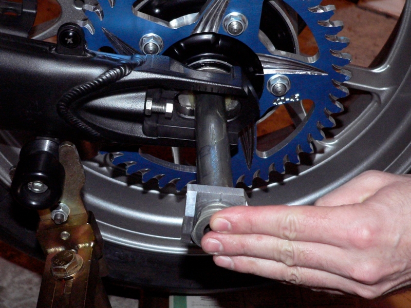
40. Place the other adjuster block in the swing arm on the threaded end of the rear axle. Place the axle washer and the axle nut on the threaded end of the rear axle.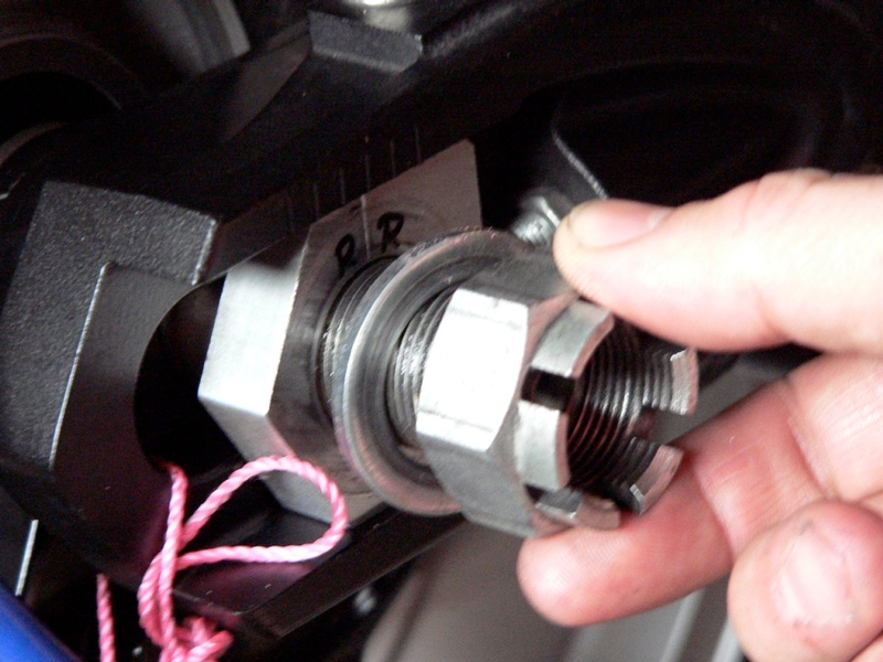
41. Seat the rear wheel against the adjuster bolts by applying several blows to the back of the tire with a rubber mallet or the fist. 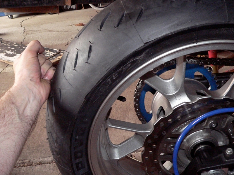
42. Tighten the rear axle nut with a 32mm deepwell impact socket. Torque the axle nut to 93.7 foot lbs. 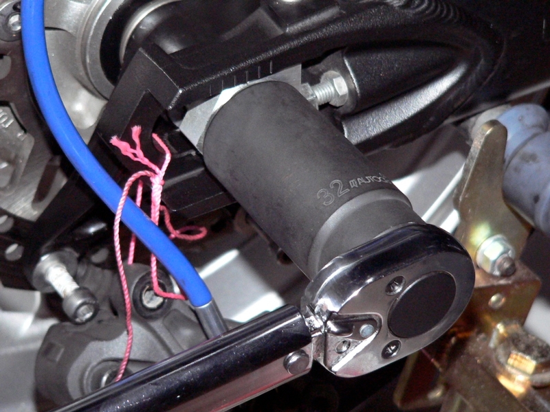
If the cotter pin hole does not match up with a slot in the axle castle nut, tighten the nut to the next alignment.
Loosen the axle nut back to the previous alignment then tighten to spec again. If you try that a few times, you will probably get the axle nut and cotter pin hole to match up. Takes several tries fiddling around, usually. 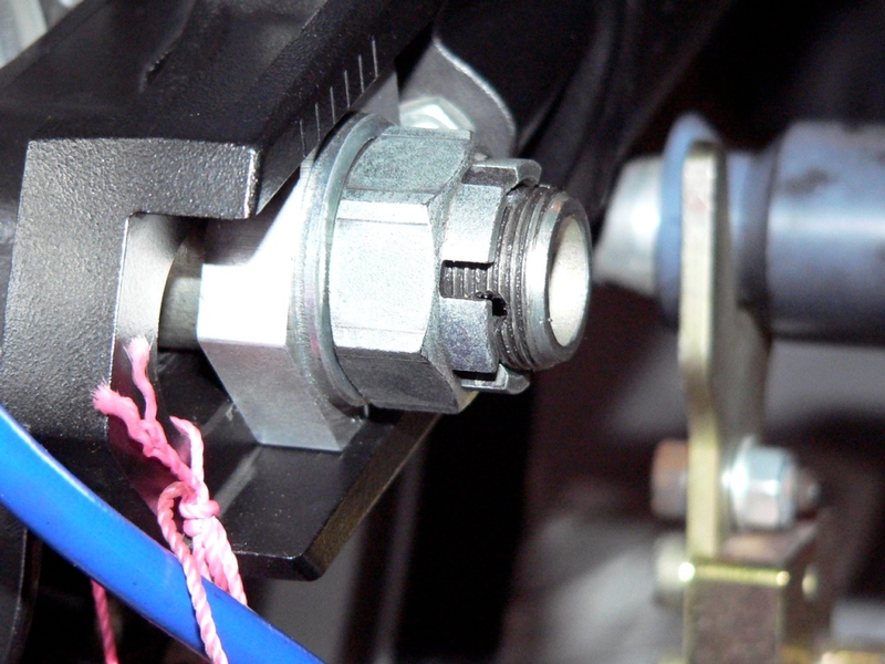
43. Insert a new cotter pin through the axle nut slots and the cotter pin hole in the end of the axle threads. 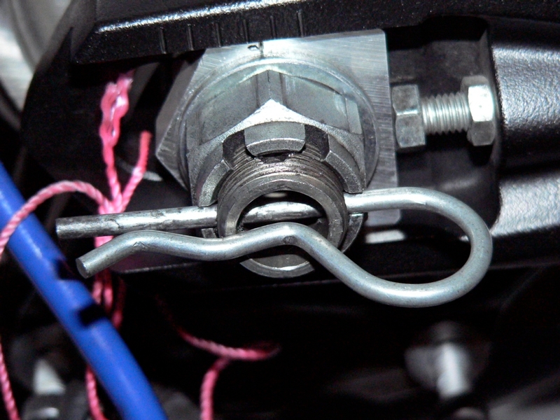
44. Untie the rear brake caliper from the swing arm and install it to the rear brake caliper mounting plate (see BRAKE CALIPER REMOVAL, steps 8 through 11).
* Last updated by: Rook on 2/25/2018 @ 6:53 PM *

 ).
).