


Auto Tune Under Seat Installation
The auto tune module is used to generate fueling adjustments that may be applied to the current mapping of a Power Commander. Dynojet makes Auto Tune for PC3, Auto tune-200, Wideband2 and possibly other modules that work with different kinds of Power Commander networks. Contact Dynojet to be sure the Auto Tune device you purchase is appropriate for your setup. The device that works with my PCV is Auto Tune-200.
There is no reason at all to use AutoTune over Wideband2. The WB2 is about $40 more but it has more adjustments through the LCD-200 for reading tach, AFR and rpm than Autotune. WB2 with the LCD-200 can also be used to access any channel with a 1-5 v sensor--so you can pick any sensor you want to receive data from if the WB2 does not already have that channel in its repertoire. If you're willing to tap into OEM sensor wires, you don't even need a PCV to use the WB2 to receive data. If you have a PCV, you can use WB2 to tune AFR just like you would with AutoTune plus the data channels you receive are more configurable with a data logging device.
This tutorial is only for installation and initial setup. I will cover the use of Auto Tune in a future tutorial.
Tools:
appropriate electrical contacts
tape
zip ties
straight slot micro screwdriver
self adhesive backed velcro
test light
Do First:
Install Power Commander V Under Seat
Remove PAIR or Block Clean Air System
Remove Sprocket Cover only, no need to remove clutch slave cylinder, See steps 1 and 4 of Sprockets/Drive Chain Removal
Remove Fuel Tank, steps 1 through 10 of Fuel Tank Removal
1. The location of the Auto Tune O2 sensor could effect the reliability of your exhaust sampling. Many suppliers of aftermarket exhaust systems will weld the bung in for you. It would be a good idea to be certain the location is far enough from the engine to allow for sampling an even mixture of exhaust gasses from all cylinders. On the other hand, exhaust samples that are taken farther from the engine will be cooler and possibly be disrupted by muffler reverberations. There are varying opinions on the best location for O2 sensors. The LH side of the exhaust will provide the best location to keep the sensor concealed and prevent it from protruding to the side of the bike.
O2 sensors have been known to require replacement because of rust. It is always important to position an o2 sensor bung a minimum of 10° above horizontal. This will help prevent moisture from settling in the sensor and damaging it. Before mounting the bung at the angle and position you prefer, be sure the sensor that protrudes outside of the pipe will clear all surrounding parts.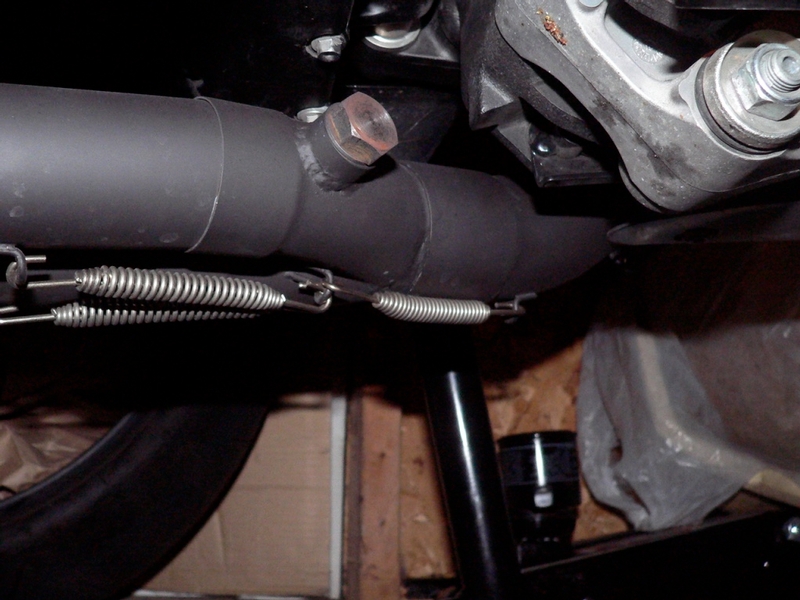
View of my O2 sensor bung from the LH side of the bike. My exhaust is a 4 into 2 into 1. The location of the O2 sensor is sampling exhaust mostly from cylinders 1 and 2. I may relocate the sensor a few inches downstream in the future and if possible right on top of the pipe to get dead center on the flow from all cylinders.
2. There are a number of switched 12v power sources and ground locations that may be used for the Auto Tune module. Depending on the power and ground source, different types of contacts may be attached to the power and ground wire of the module. The rear brake light connector is right under the seat. It is a convenient source of power and ground for an underseat install of Auto Tune provided the rear brake light lead is disconected. The power and ground wires may be trimmed shorter if desired. Attach appropriate electrical contacts to the ends of the black and red wire housed in the stiff plastic tube that comes off of the Auto Tune module.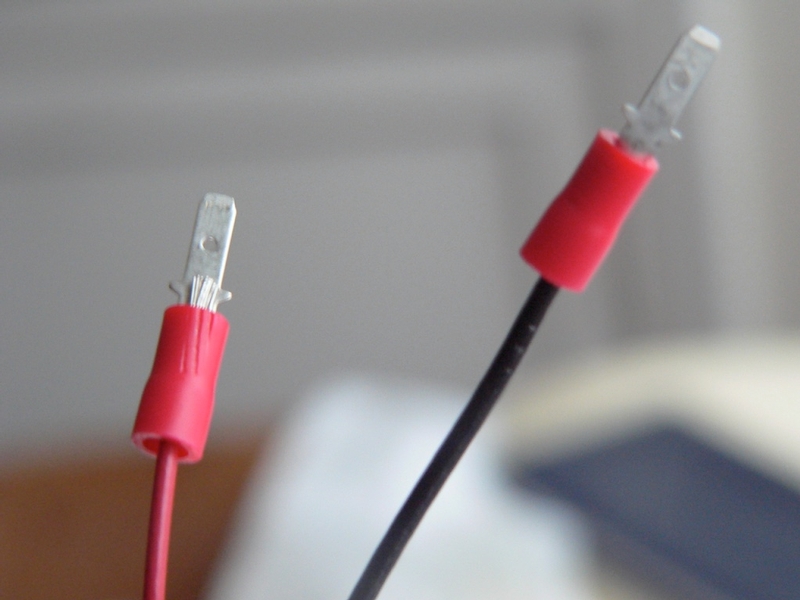
Normally, the rear brake light leads are not connected if the rear fender has been removed (see DIYRear Fender Removal and DIY Fender Eliminator http://www.zx14ninjaforum.com/messages.cfm?threadid=CE80FE5C-D56B-84E2-151AB9DA30FE0878 ). I was able to find some very small crimp on electrical contacts from my local motorcycle dealership. Similar contacts can be purchased at Radio Shak or a hardware store but you will probably need to use some emery paper and a file to make them small and thin enough to fit the female contacts of the rear brake light lead.
3. Connect the CAN cable supplied with your Auto Tune kit to either of the ports on the Auto Tune Module. Insert the small plastic CAN cable terminator plug into the other port of the Auto Tune module. The terminator plug must be inserted in the open port in order for the module to function.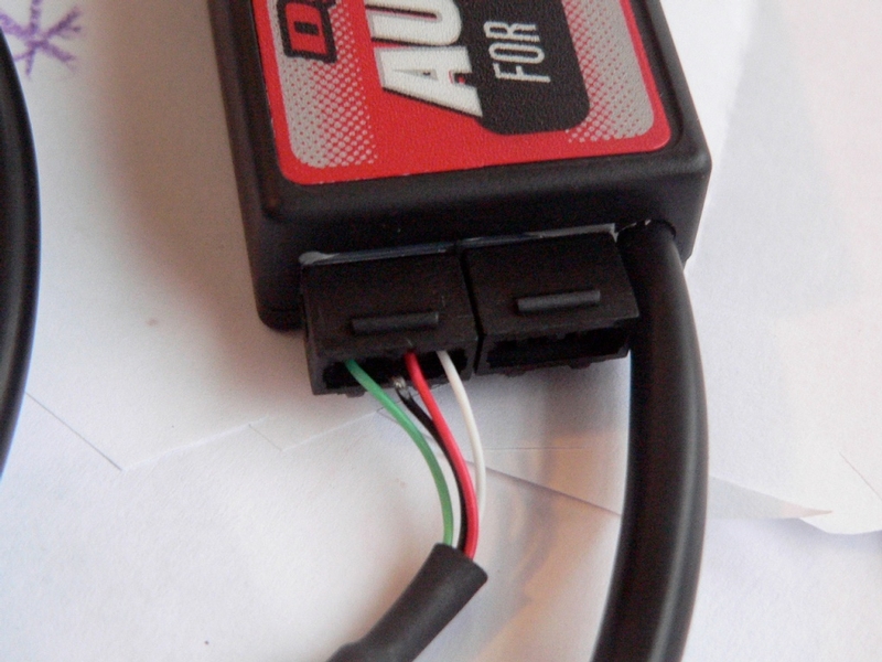
4. Remove the plastic cap from the O2 sensor. Do not remove the anti-seizing agent applied to the threads, this will prevent the threads from rusting. Install the sensor to the O2 sensor bung in the pipe. There is no exact torque spec for the o2 sensor. The crush washer on the seat of the sensor will seal it so approximately 5~7 foot pounds of torque should be adequate.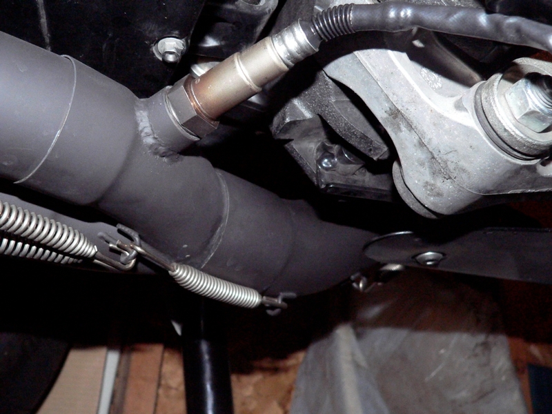
5. Connect the O2 sensor harness leads. 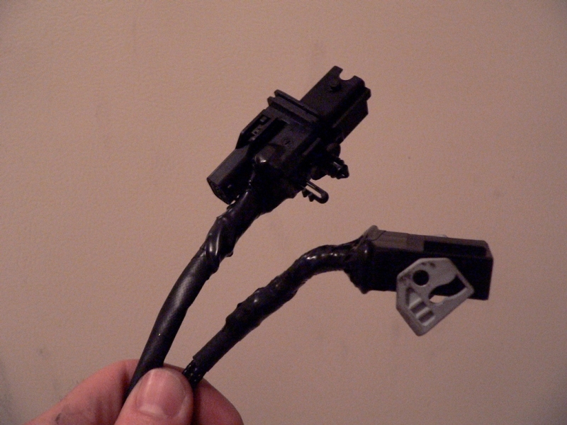
Wrap the loose wires on the free end of the harness with tape.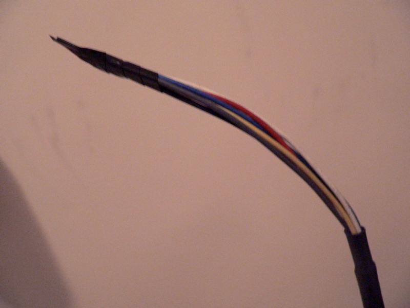
6. Rout the free end of the O2 sensor harness behind the water pump on the LH side of the bike.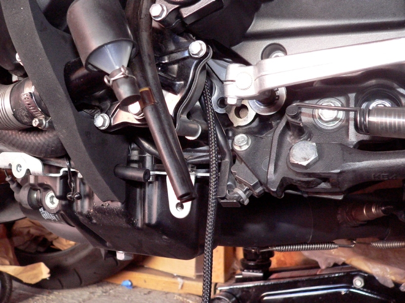
The O2 sensor harness should be routed under the sprocket cover as shown below. I removed the OEM wire retainer and ran the sensor harness through it along with the OEM wires.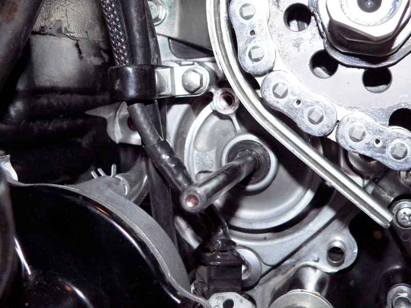
Guide the O2 sensor harness over the rear engine mount on the LH side of the bike.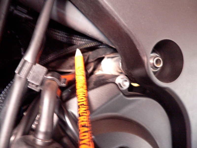
The free end of the O2 sensor harness should be guided under the rear fuel tank mounting bracket to the under seat compartment where the PCV is located.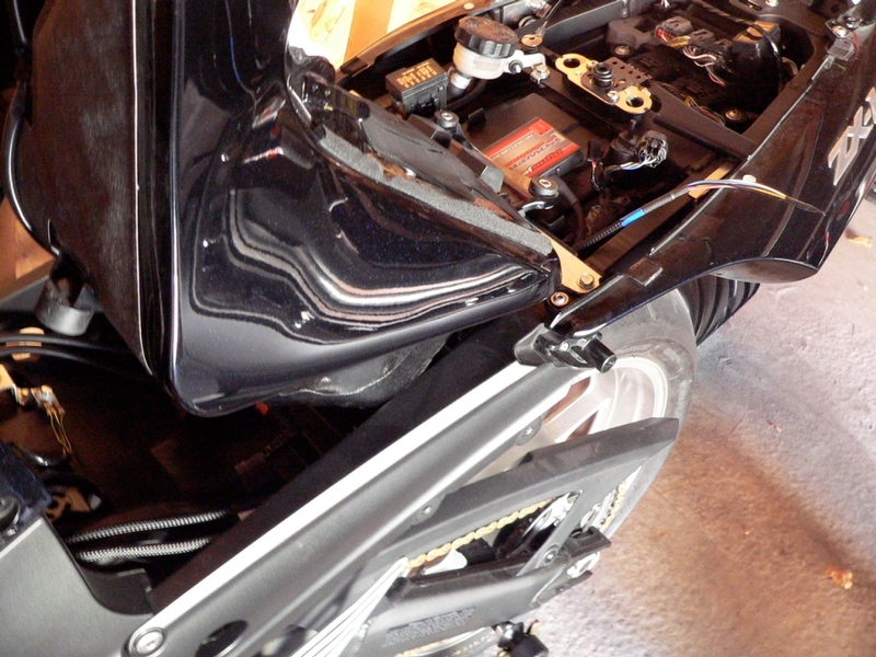
7. The O2 sensor harness leads are tucked in front of the shift lever. 
The O2 sensor harness leads are secured to the water pump with a zip tie.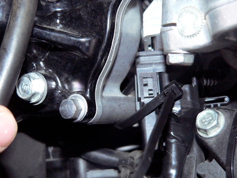
The O2 sensor wire is secured with a zip tie to the frame near the sensor.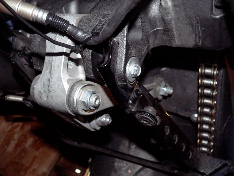
8. Remove the tape from the wires at the free end of the O2 sensor harness. Use a straight slot micro screwdriver to attach the wires from the O2 sensor harness to the appropriate holes in the Auto Tune module as shown. With the module turned over and the connector holes pointed at you the order from left to right is: Blue, Red, Yellow, Black, Grey, White.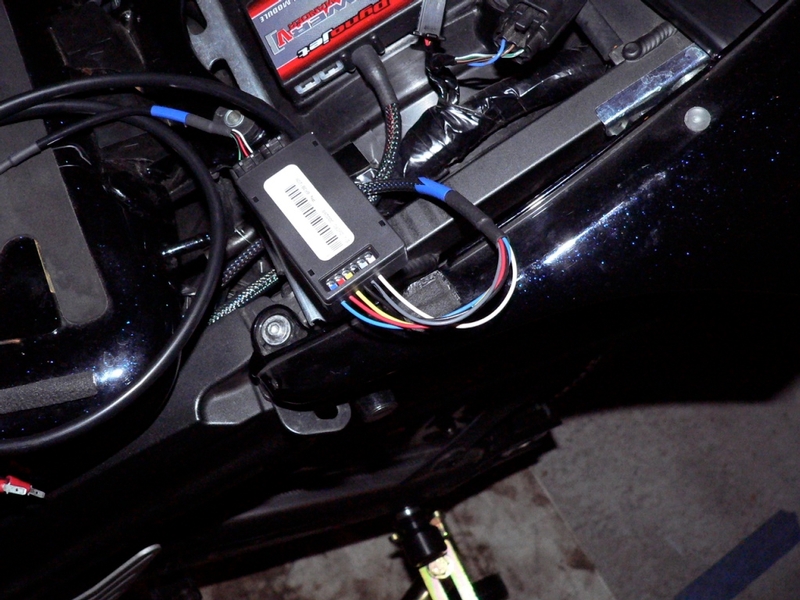
If these wires do not seem to go in as far as they should, flatten the tinned ends by squeezing with a needle nose pliers so the ends will pass under the screws.
9. Secure the Auto Tune module with self adhesive backed velcro and connect the CAN cable to either port of the PCV. The open port on the PCV must have a terminator plug inserted into it in order for the modules to function properly.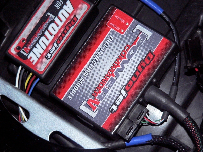
10. The power/ground wire tube should be routed to the location of the rear brake light (or wherever you plan to connect these wires). I coiled mine up and placed it under the ECU to avoid the need to cut it shorter.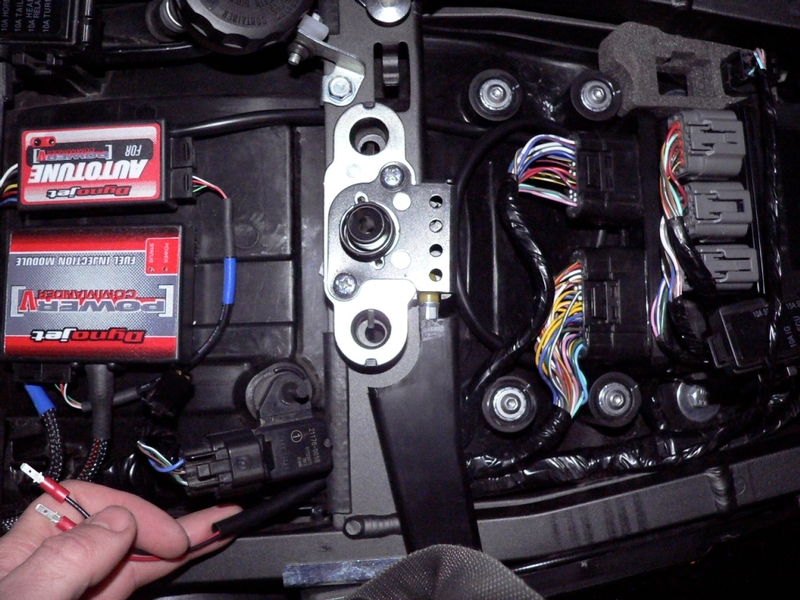
11. Insert the contacts to the rear brake light lead connector. Wrap them with electrical tape to hold them in place. I do not believe it matters which male contact goes to which female in this situation. A test light will be helpful if +/- female contacts can be identified at the rear brake lead connector. Otherwise, refer to the picture below for reference. I may have gotten lucky when I connected mine. 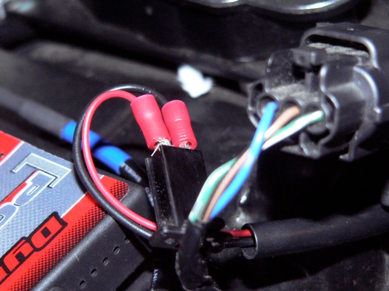
The tail light circuit (license plate light, tail light, brake light, city lights and something to do with the multifunction meter) has 10 amps available. I have an LED tag light and no city lights, and 0.03 amps were drawn when AutoTune was not connected. Activating the brake light caused the amperage to rise to 0.25. I would estimate a bike with all stock appliances would draw about 3.5 amps or less. According to my multimeter, AutoTune draws 0.01 amps even when the bike is off. I’m not sure how it draws any power with the ignition switch OFF but it does. When the Ignition is turned ON, the draw from AutoTune varied with readings up to 1.68 amps, probably from the O2 sensor reacting to fresh air in the exhaust system. When the engine was started, the amp draw continued to fluctuate and settled at 1.23 amps. Without running a constant test of Autotune under various exhaust situations, it’s probably safe to assume the most it will draw is about 2 amps. So, a stock bike with AutoTune connected to the tail light circuit will place a total max load of about 5.5 amps on this 10 amp circuit.
12. The Auto Tune wire is zip tied to the PCV wire with is secured to the underside of the LH frame rail (see PCV Underseat Install, steps 24 through 26).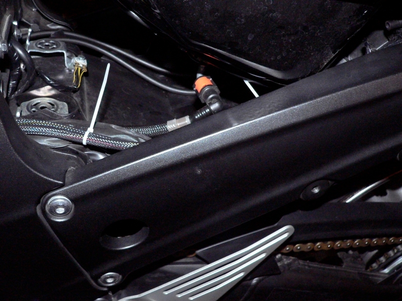
13. You will need a computer with Power Commander 5 software opened. Connect the computer to the PCV (see Dowloading PCV Software To Your Computer in the introduction of PCV v 1.0.6.4, see also step 2, 3 and 9 through 13).
Enable Auto Tune in your PCV network (for other info, see PCV v 1.0.6.4 1.0.6.4, step 30).
Go to Power Commander Tools > Configure > Feature Enables and Input Selections.
Select the On/Off check box for Auto Tune.
Go to Auto Tune > Configure
Select or deselect the Require Run Time check box.
I suggest that you select this box. In most cases, you will want the engine to run under normal, stable conditions before Auto Tune starts creating trims.
Input at least 120.000 seconds in the Minimum Run Time box to avoid trims made immediately after the engine starts. It is doubtful you would check trims until the engine has been thoroughly warmed up, anyway.
Select or deselect the Require Engine Temp check box.
I suggest you deselect this box when you first start using Auto Tune. When you become familiar with Auto Tune and your engine, you may wish to prevent Auto Tune from making trims until the engine has reached a certain temperature.
If this function is used without much experience with Auto Tune, I would set the Minimum Temp to no more than 100. Operating temperature could vary according to ambient temperature and other factors. Setting Minimum Temp too close to optimum operating temperature may be confusing if you do not actually know what that temperature is. Again, you will always be warming your bike thoroughly before checking trims so the minimum temperature is not that relevant.
Input Max Enrichment Trim (%)
Input Max Enleanment Trim (%)
I suggest that you keep your maximum and minimum trims very small until you become more familiar with Auto Tune. You may need to do many more tuning runs to achieve your optimum AFR but accepting small trims will be safer than accepting large trims.
Select the Number of O2 Sensors your PCV is equipped with.
Unless you have a special setup, this should be 1
Click OK to accept the present data entered in the Auto Tune Configuration box or click Cancel to close the window without changes.
Install Sprocket Cover, See steps 53 through 57 of Sprockets/Drive Chain Removal.
Install Fuel Tank, steps 11 through 15, Fuel Tank Removal
The o2 sensor should be tested periodically to determine if it is functioning properly. Dynojet recommends removing the O2 sensor from the bung (I don’t believe it should be necessary to do this if the bike has not been run for a couple of days). Hold the O2 sensor in uncontaminated ambient air and turn the ignition switch ON to power up the Auto Tune module for at least 1 minute. The LED on the Auto Tune module will be constant when fully powered up. Use a ballpoint pen or other round tip instrument to press and hold the Function button located next to the LED on the Auto Tune Module for 3 seconds and then release it. The LED should blink rapidly, pause and then begin to flash. Count the number of flashes and refer to the chart below. 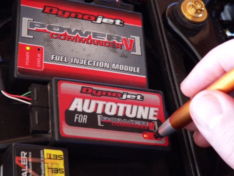
A normally functioning sensor may not blink when tested at very low elevations. I have had my O2 sensor in for seven years and it is still testing normal. However, it may be best to remove the sensor and plug the bung with the special bolt if Auto Tune will not be used for a long time.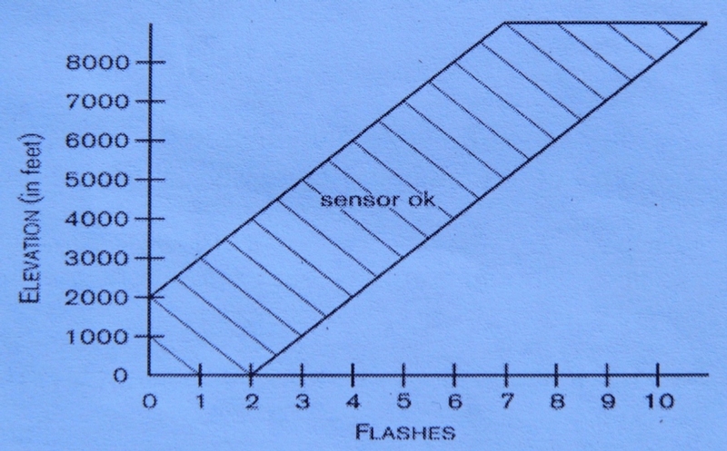
* Last updated by: Rook on 6/4/2018 @ 8:53 PM *