


How To Use The Sync-Pro Carb Tuner and the ABN Vacuum Gauge Carb and Throttle Bodies Sync Tool
I’m including procedures for both the SyncPro and vacuum gauge sync tools but I recommend vacuum gauges over the SyncPro.
Here's a few other threads where the topic is discussed.
SyncPro v ABN Sync Gauges
How to Synchronize Engine Vacuum
How-To for throttle bodies sync?
Throttle body sync tip
It's assumed that steps 1~10 of my Engine Vacuum Sync tutorial have been followed before starting the procedures in this tutorial. The PAIR should have been disabled, the vacuum hoses to the throttle bodies test fittings should be connected and blocked, the fairing grommets in the air box should be taped, the engine should be warm and idle speed set. There is often a lot of switching of hoses in calibrating a SyncPro or a set of vacuum gauges. It is not always convenient to shut the engine down to switch a hose so be mindful about blocking the test fitting hoses or test fittings ASAP when they are not in use. Leaving the hoses unblocked could result in sucking harmful particles into your engine if it is running.
Any test fitting will do just fine for calibrating a SyncPro or a vacuum gauge sync tool but it is best to use the the cylinder with the highest vacuum. With the hoses already connected to the test fittings, unblock each hose one at a time and test its vacuum level on the tool. If you are using vacuum gauges, use the same gauge to test all hoses. If you are using a SyncPro, test each hose on the calibration manifold using some additional hoses to connect the manifold to the SyncPro as shown in step 4 of this tutorial. It will be fine to quickly connect and disconnect hoses with the engine running as long as the environment is clean and you immediately block each hose after removing it.
SyncPro
The long tubes of a fluid manometer can be read and compared very precisely which is the main advantage to using it. The manometer displays the difference in vacuum across the four throttle bodies by the height of fluid sucked into each of the manometer tubes. However, it is very important to note that the SyncPro manometer does not measure vacuum quantitatively. For this reason, determining if the engine vacuum is in spec is not possible. Technically speaking, the SyncPro is not designed to be calibrated. You might want to see if you can get your hands on theseThrottle body sync tip
What you do is balance the fluid columns of the SyncPro, not calibrate. In order to read the tool properly, the four valves on the fluid reservoirs must be adjusted so that a given amount of vacuum will effect all reservoirs equally. If the valves restrict all of the reservoirs equally, the fluid in all of the reservoirs will be drawn to the same height when the engine vacuum is synchronized. The vacuum resistance must be equalized before each use of the tool in order to read it accurately. If you don’t finish your sync in one day, you may want to check the calibration of the tool when you resume the next day.
1. A hose should be connected to each throttle bodies test fitting. A restrictor should be inserted in the end of the hose that is closest to the fitting. The hollow bottom of the restrictor should be situated so it will face the fitting as shown below. Use a golf tee or tape to block the free end of each hose and hang them over a handlebar. It’s also a very good idea to number the hoses for positive id while you are working.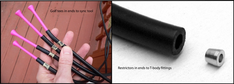
2. If the reservoirs of the SyncPro are low, disassemble the tool and remove the reservoir valves per the SyncPro instructions. The assembly instructions are well illustrated and easy to follow. Fill each reservoir to the same level with SyncPro manometer fluid. The level should be 1/4’ to 3/8” below the threads at the top of the reservoir.
Remove the rubber caps from the tops of the fluid tubes and use a small straight slot screw driver to thread each of the valves out counterclockwise until the screw stops against the body of the tool (not tight, just until it stops). All valves are now at maximum restriction. 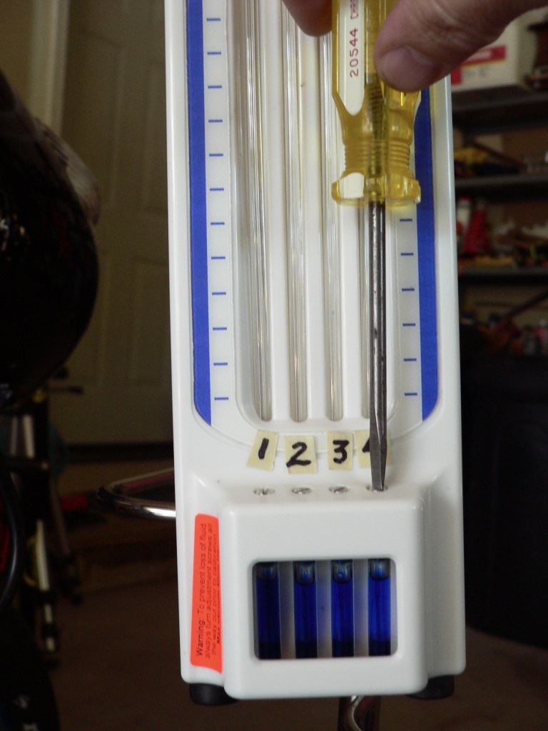
Be sure you turn the screwdriver counterclockwise or you may experience having fluid sucked out when you start the motor. This will not hurt the motor but you will need to take the tool apart and refill it.
I have placed a piece of tape above each reservoir to avoid mistakes and make reading the tool easier during the calibration and sync.
3. Connect four lengths of extra hose between the calibration manifold and the SyncPro. Block one of the remaining open fittings on the calibration manifold with a rubber cap so that only one fitting is open.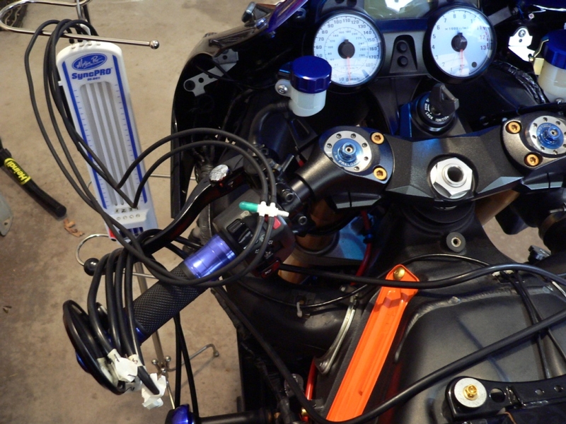
Extra hoses purchased at an auto supply are connected between the SyncPro and the calibration manifold. The SyncPro hoses with restrictors are connected to the test fittings on the throttle bodies with the free ends blocked with tape and hanging over the hand grip.
4. Unblock the free end of hose #1 and connect it to the calibration manifold. Leave the other hoses to the test fittings blocked with golf tees or tape.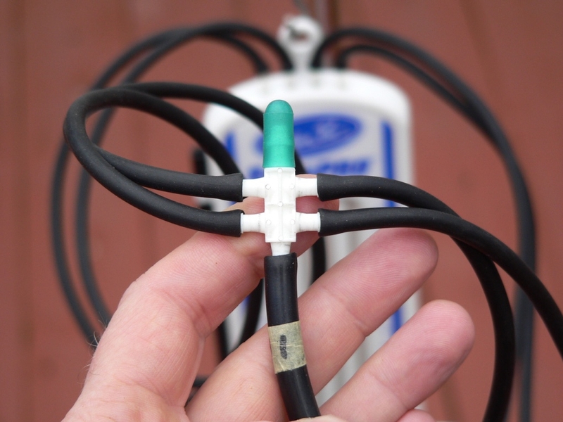
The Sync-Pro instructions say to use the test fitting on the “master” carb or throttle body for calibration of the manometer. A master throttle body would be preset to max flow and have no adjustment. All of the Gen1 ZX-14’s throttle bodies are adjustable so it has no master. Therefore, it is up to you to find the test nipple with the highest vacuum. Using this method with all hoses connected to the nipples will be much easier than using the calibration hose supplied with the SyncPro. Warning: You may experience fluid clogs in the next few steps. Consider this training for dealing with the problem during the sync.
5. Start the engine and let it run until it goes to normal idle. View the fluid columns on the Sync-Pro. Mark the height of the highest column with a line and the number, 1 to id the vacuum level of cylinder #1.
Remove hose #1 from the test manifold blocking the hose with a golf tee immediately. With vacuum removed from the tool, the manometer fluid will returned to the reservoirs. If any fluid drops are left blocking any of the fluid column tubes, refer to step 6 before proceeding. If no drops have blocked the tubes, remove the tee from hose #2 and connect it to the test manifold. Mark the height the height that fluid is drawn in the highest fluid column for cylinder #2. Repeat this procedure with hoses #3 and #4.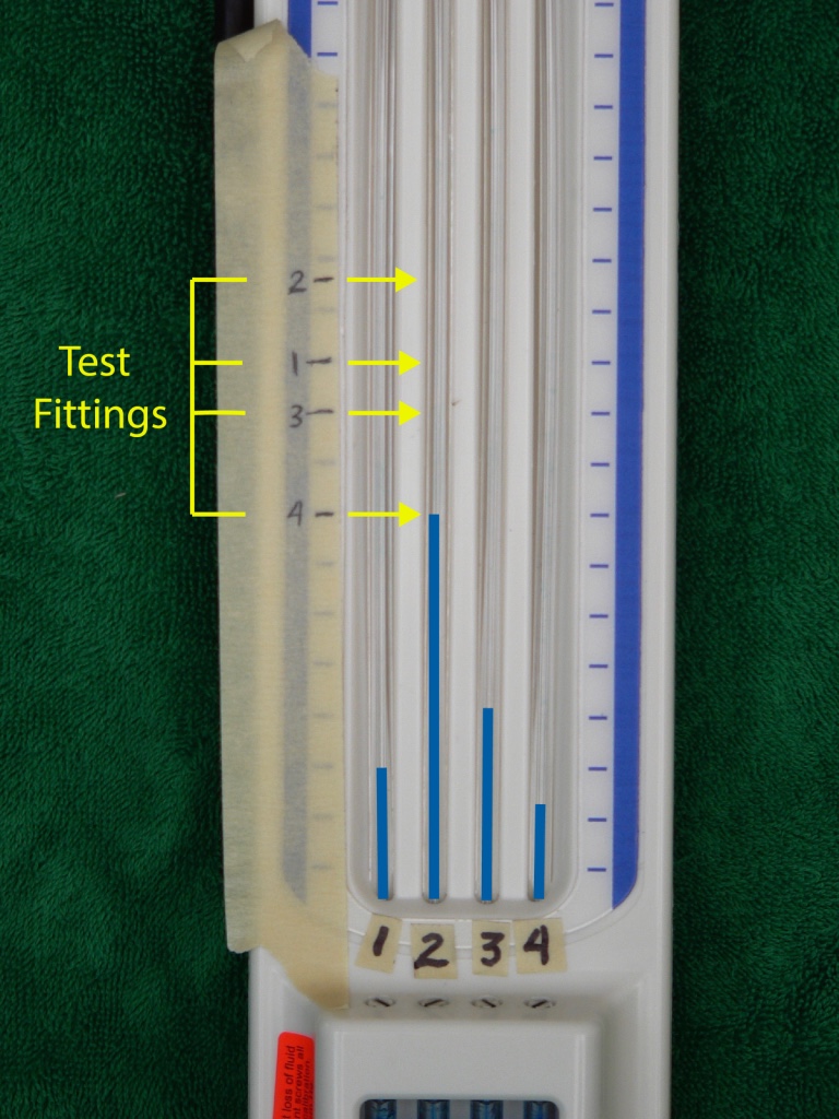
With all valves at max restriction, the fluid rose the highest in column 2. Cylinder #2 pulled the fluid highest in this column and cylinder #4 pulled the fluid least high. Cylinder #2 is the best cylinder to use for calibrating the SycnPro because cylinder #2 has the highest vacuum.
6. If fluid droplets block the tubes after the fluid returns to the reservoirs, the fluid columns will react entirely different to vacuum in those tubes. If the fluid has been used previously or if the engine ran for more than about 5 minutes, there’s a good chance droplets will stick in the tubes after vacuum is removed. If this happens at any time during calibrating or during the syncing process, the droplets must be cleared before you can use the tool again.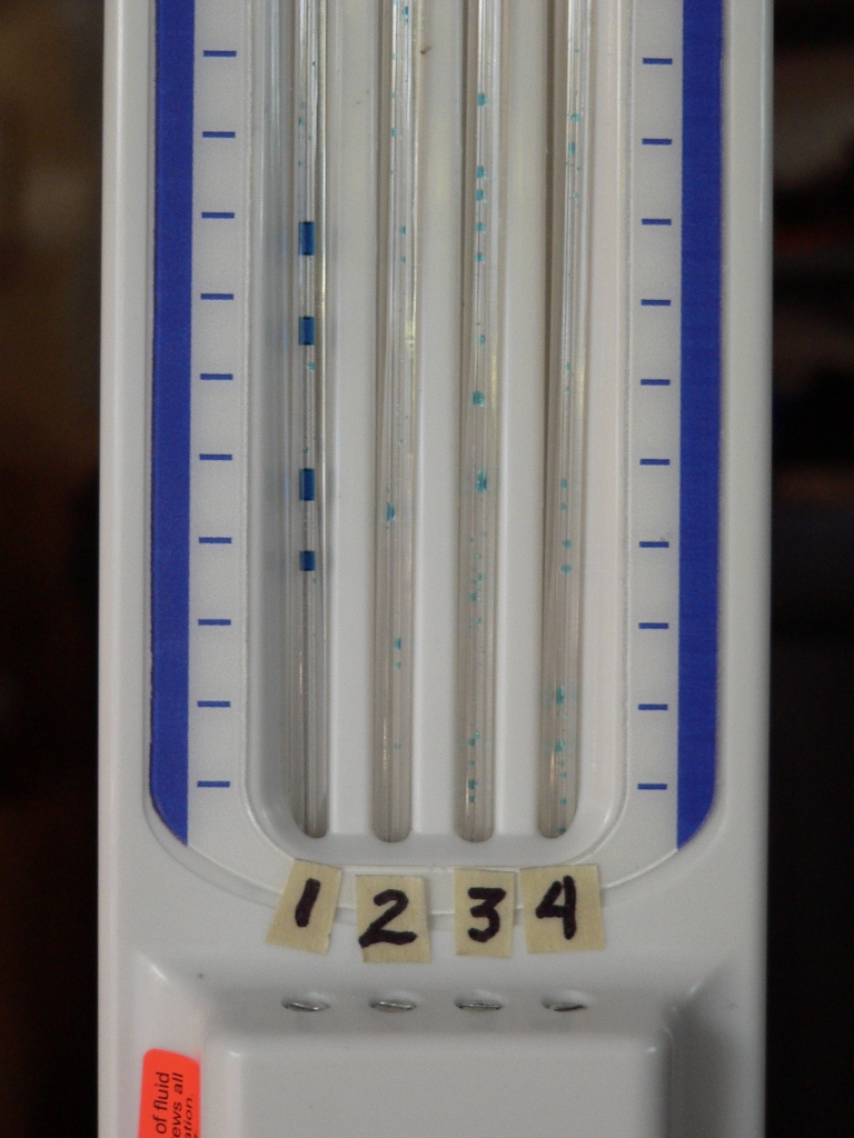
Disconnect the hoses from the Sync-Pro. Grasp the tool with both hands and wave it at the ground forcefully as if you were shaking down a thermometer. The centrifugal force will pull the droplets in the fluid tubes down to join with the rest of the fluid in the reservoirs. Reconnect the vacuum hoses to the Sync-Pro and the tool is ready for use. 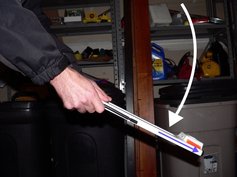
7. After determining which cylinder is producing the highest vacuum, connect it to the calibration manifold and run the engine.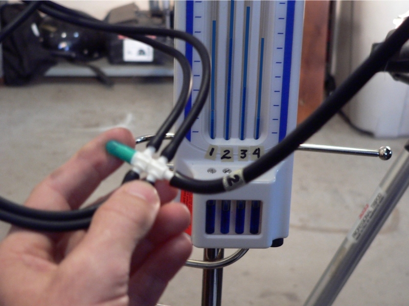
The picture above shows that valve #2 is least restricted, rising to the highest mark among the 4 columns. Valves #1 and #4 are most restricted rising only to the ninth and eighth mark, respectively. As you can see, it would be possible to observe which valves need to adjusted and how much using any of the hoses from the test fittings. They all will cause the fluid to react in similar fashion but the hose with highest vacuum will draw the fluid the highest which reduces your margin of error.
8. Use a small straight slot screw driver to turn each of the more restricted valves clockwise until the fluid columns from those reservoirs match the height of the least restricted. Now the Sync-Pro is calibrated. 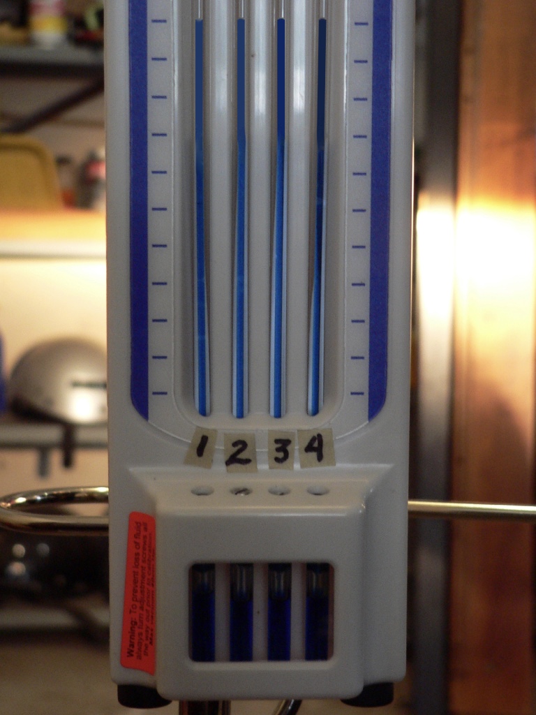
All fluid columns were drawn to the highest level among the four fluid columns after the valves were balanced.
9. Shut the engine off, remove the extra hoses from the SyncPro and remove the calibration manifold from the hose you used to calibrate. Connect all four test fitting hoses in the proper order directly to the SyncPro. Now you are viewing the relative vacuum levels among the four throttle bodies. You can perform the engine vacuum sync starting from step 11 of the Engine Vacuum Sync tutorial.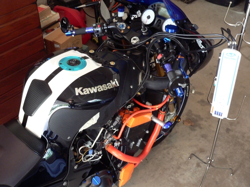
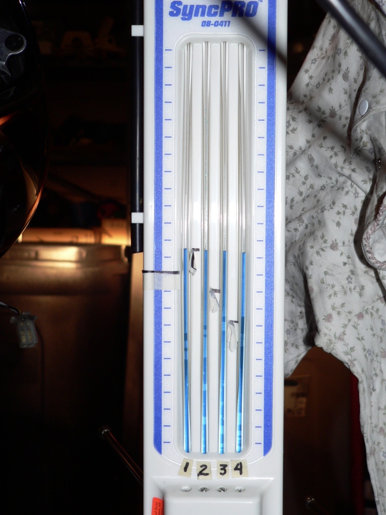
I used tape marks to identify the height of the columns before any adjustments took place. The engine vacuums are synchronized when they are adjusted so that all four fluid columns are the same height. As you can see, it was night time. It was a very long day.
ABN Vacuum Gauge Sync Tool
Vacuum gauge sync tools will not only allow you to balance the vacuums in the throttle bodies but they will also tell you what the vacuum is in cmHg. This enables you to sync the throttle bodies so that they are producing the service manual specced vacuum. I researched the affordable vacuum sync gauges currently available online thoroughly and it appears none of them have increments in mmHg, only cmHg. The service manual specced tolerance for induction vacuum measurement is +/- 10mm mercury. From my experience, such exact measurement would not be crucial for good engine performance. It’s possible to make a close estimate of mmHg on the large dials of the ABN sync gauges. A couple mmHg more or less will not be significant to performance.
1. If any needles are not indicating “0” when the tool is not in use, carefully pry the lens off the gauge to access the calibration screw. Use a micro screwdriver to turn the calibration screws until the needles are zeroed. 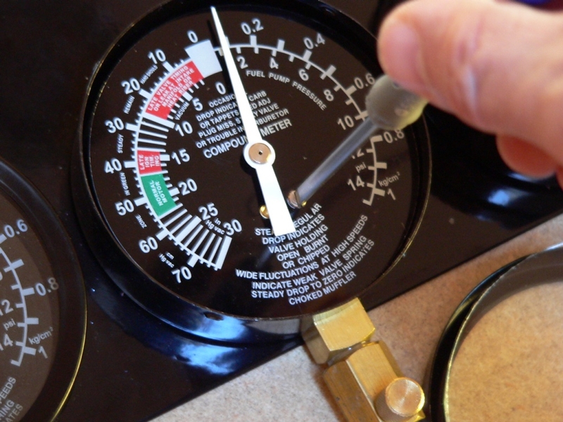
2. Some vacuum gauges have dampers that are inserted in the hoses (similar to the restrictors used with the SyncPro) to prevent needle flutter. The ABN vacuum gauges are equipped with adjustable damper valves. Start and thoroughly warm the engine. Set idle speed. Unblock and connect the hoses from the throttle bodies test fittings to the gauges. If a gauge needle flutters when it is connected to the test fitting hose, the gauge requires that it’s damping be adjusted. Adjust the damper valve by turning the small nob on the stem of the gauge, stopping as soon as the needle is steady. 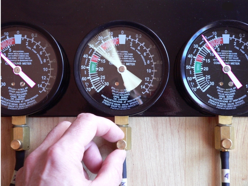
3. After zeroing the gauges and adjusting damping, check the calibration of the gauges with vacuum applied. If all four gauges were zeroed while under no vacuum, they are probably all reading accurately while under engine vacuum. You will first need to try each of the four test fitting hoses on the same gauge to find the hose with the highest vacuum. Just be sure to block each hose as soon as it is removed from the vacuum gauge to avoid sucking in debris. Check the balance of the ABN vacuum gauges by connecting each gauge one at a time to the test fitting hose with the highest vacuum. If all gauges register the same value the gauges are balanced. Just like checking balance with the SyncPro, it is possible to use any test fitting hose but the one with the highest vacuum will be the best to use.
You may use a measured vacuum source to verify calibration. I used the gauge on my mightyvac vacuum pump. A highly accurate vacuum gauge attached to the pump would be best but since both tools indicated the same readings on all gauges so I considered that to be conclusive enough for a DIYer.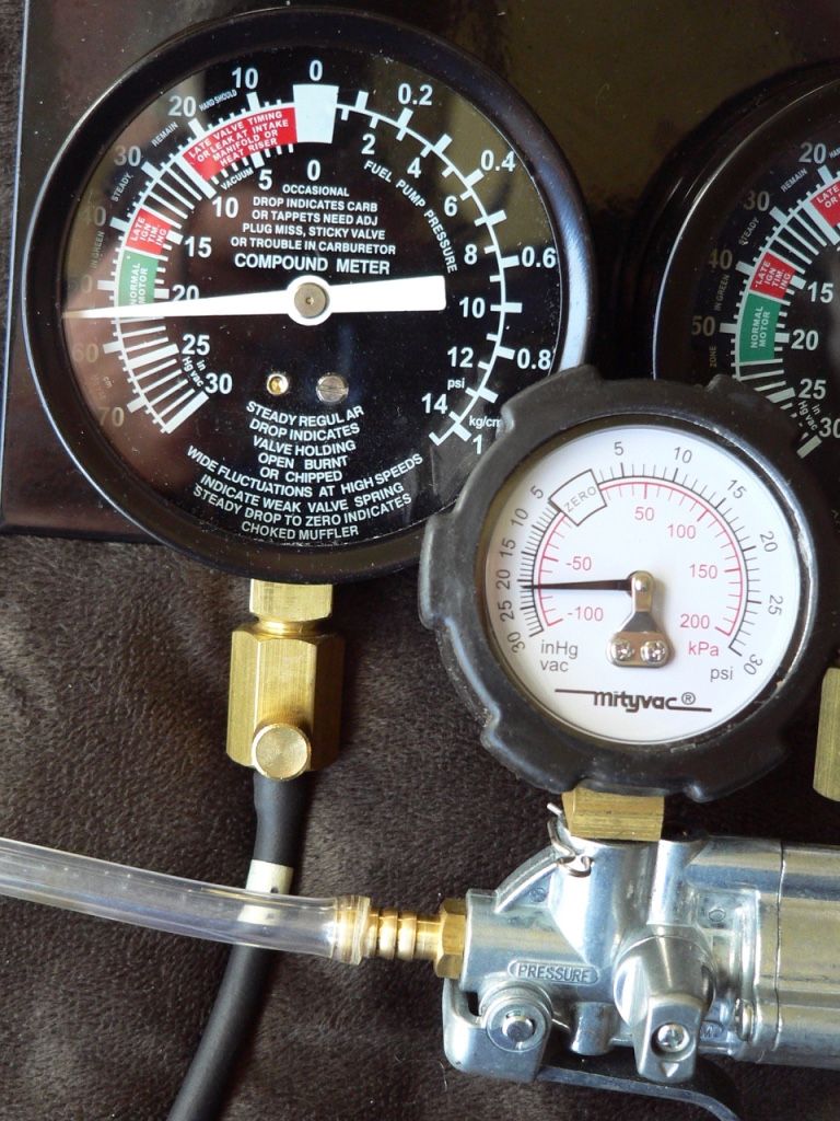
I tested calibration of each gauge on my ABN sync tool using my mityvac vacuum pump. The mityvac is producing 21 inHg according to its gauge and the ABN gauges also each indicated 21 cmHg. The mityvac and the ABN gauges indicated the same readings at higher and lower vacuums than 21 inHg as well. I also tested the ABN gauges against my Sync-Pro manometer’s reading. When all the engine vacuums were synced, both the ABN and the Sync-Pro showed equal vacuum on all cylinders. You are probably pretty safe to assume a brand new ABN sync tool is accurately calibrated and balanced as long as you zero it.
After zeroing, it’s possible that a gauge may not indicate the same value as the others when you test with the hose that has highest vacuum. If this should be the case, remove the lens and adjust the calibration screw with the gauge under vacuum until it indicates the same reading as all others. If an adjustment to calibration is required, it is ok if that gauge no longer is at “0” when vacuum is removed.
4. Connect the hoses from the test fittings in proper order and perform the vacuum sync starting from step 11 of the Engine Vacuum Sync tutorial. The gauges are used to determine the changes in vacuum in the throttle bodies in the same way a manometer is. When all gauges indicate the same value, the throttle bodies vacuum is synchronized and you may also determine if it the vacuum is in spec.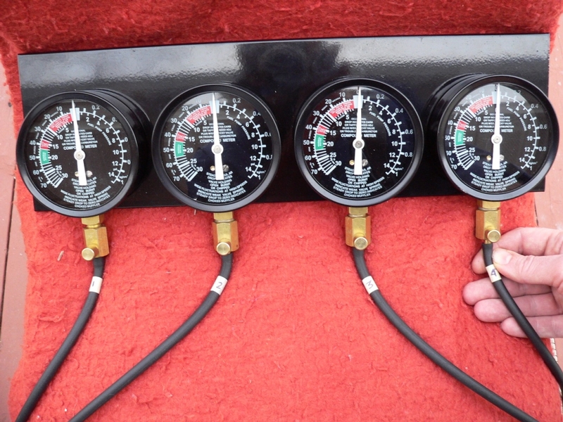
* Last updated by: Rook on 12/30/2017 @ 10:38 AM *