Move Close
Welcome to zx14ninjaform.com!

You are not logged in.
New Topic Reply
Next Page

Page: 1 2 3

Previous Page

Thread: Valve Clearance Check and Adjustment

Created on: 01/13/12 02:14 AM

Replies: 64

Rook


Rook's Gravatar

Joined: 03/28/09

Posts: 20577

Valve Clearance Check and Adjustment
01/13/12 2:14 AM

Valve Clearance Check and Adjustment, Gen 1

Introductory Notes

Time and Cost
Before committing to doing your own valve clearance check, be aware that it will probably require at least a few full days if you do not have a great deal of wrenching experience. Further, the valve clearance check may determine the need for adjustments of the clearances and that will double the amount of work. There are some short cuts that you might take but this is not something to expect to get done in a weekend. I think a safe estimate for the check and the adjustment is 30 to 60 hours for a novice.

The disassembly of the parts presents quite a few opportunities to execute other maintenance jobs. If you choose to do some or all of these, that will require additional time.

The cost of replacement parts is approximately $130. The tools required to do the job (other than the common ones you may already own) will cost about 30 dollars.

Work Environment Requirements
It is not advisable to measure the valve clearance in an environment that is colder than room temperature. If the work space is not heated it will probably be best to choose a time of year when the weather is mild to warm. Keep in mind that the project could take several weeks if you are not able to devote a large percentage of your time to it.

The engine will need to be open for part of the time while the job is in progress. It should be protected with dust covers but it will still be best to do the work somewhere that is as clean as possible and will not have dust getting stirred up.

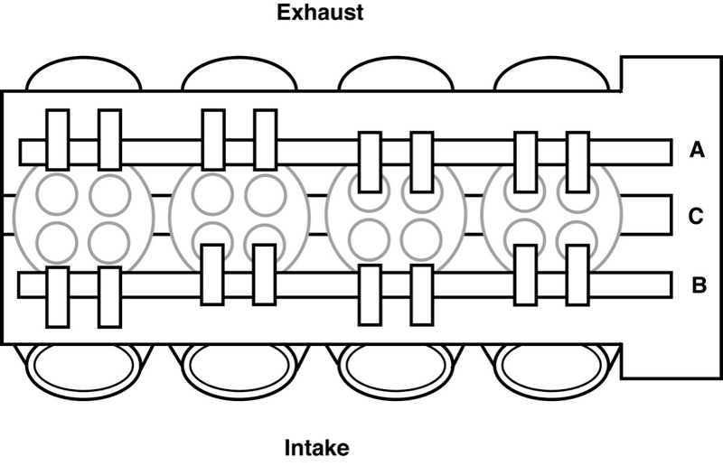
Engine Configuration
The four cylinders/pistons are named #1, #2, #3, and #4. They are in numeric order from #1 on the left (clutch lever) side of the bike to #4 on the right (front brake lever ) side of the bike. Each cylinder has two inlet valves and two exhaust valves. In this tutorial, I refer to the inlet valves as Left Inlet Valve and Right Inlet Valve. The Exhaust valves are referred to in the same way, Right and Left. The exhaust valves are arranged in a row toward the front of the motor where the exhaust system starts. The inlet valves are the row toward the back of the motor where the four intakes come down to the engine.

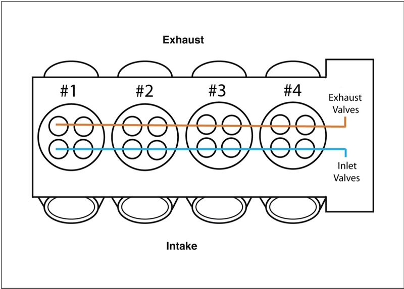
The crankshaft [C] at the bottom of the motor is driven by the pistons. The Crankshaft turns the camshafts by a system of sprockets and a chain. There is a camshaft [A] for all of the exhaust valves and a separate camshaft [B] for all of the inlet valves.


Camshaft, Lifter, Shim, Valve, Cylinder
The cams on each camshaft are egg shaped wheels. There is one cam that controls each lifter. There is a lifter above each valve and a shim between the lifter and the valve. As the camshaft turns, the high spot (the lobe) of the cam comes around and presses the lifter down. This pushes the shim and the valve stem down the guide and the valve moves farther from its seat which allows a space for fuel and air to enter the cylinder (inlet valves) or a space for exhaust to be expelled from the cylinder (exhaust valves). The valve returns to its seat under the tension of a spring after the cam lobe passes across the lifter.

Cause of Valve Clearance Change
Over time, the adjoining surfaces of the valves and the valve seats wear. This allows the the valve to rest deeper into the valve seat which in turn, allows the tip of the valve stem to slide farther up the guide. The shim at the top of the guide gets pushed higher which pushes the lifter higher. Because the lifter is riding higher, the tiny space (the valve clearance) between the top of the lifter and the cam is reduced. There are different optimum clearances for a few different types of engine applications. Some are smaller (tighter) than others. If the valve clearance is insufficient, the valves will eventually burn from having too close of contact between parts or parts will impact. Catastrophic engine failure would be the result in either case.

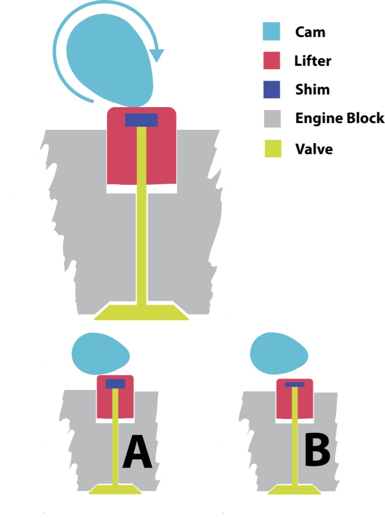
To clearly illustrate the point, the diagrams above exaggerate the size relationships between the shim, lifter and cam.

Diagram A shows a valve shim that is too thick and causes the lifter to be raised too close to the cam. It would be impossible to slide a feeler gauge blade of the smallest specced clearance between the lifter and the cam. The valve clearance is too tight.

In diagram B, the thick shim has been replaced with a thinner shim. The lifter does not ride as high atop the thinner shim. The valve clearance has been adjusted looser (larger). It is now easy to slide an appropriate feeler gauge blade between the cam and the lifter.

Top Dead Center
As you can understand, the valves travel up and down to open and close. Half of the valves are completely closed when the piston in cylinder #1 has turned to the highest point of its compression stroke. This is known as Top Dead Center (TDC) of the Compression Stroke of Cylinder #1. That is where we check the clearances of all eight of the closed valves to determine if they are in spec. The other half of the valve clearances will be checked at the Top Dead Center of the compression stroke of Cylinder #4 (TDC Cylinder #4)

In order to check valve clearance, you will need to turn your motor to Cylinder #1 TDC and also Cylinder #4 TDC. When turning the motor, it is very important that you only turn it forward. The motor should be turned clockwise as viewed when looking at the right side of the bike. This is the direction that would turn the rear wheel so that it propels the bike forward. DO NOT EVER TURN THE MOTOR BACKWARD!! The engine timing could be disrupted and cause engine failure when the engine is started.

Adjusting Valve Shims for Performance Goals
There is a range of safe clearances for the valves. The range for valve clearance is as follows.
Exhaust 0.22 ~ 0.27 mm (0.0087 ~ 0.0106 in.)
Inlet 0.15 ~ 0.20 mm (0.0059 ~ 0.0079 in.)

The rule to adjusting valve clearance is to always adjust to looser spec rather than tighter when a choice or a judgement presents itself. The reason is that valve clearance will always get tighter over time as the valves wear. The valves may make more noise when they are adjusted loose but the noise will reduce as the clearance gets tighter. Also, a safe clearance will be maintained for a longer period of time if the clearance starts out looser.

Generally, it is best to aim at adjusting your valve clearances to the middle of the spec range. That way, if the measurements to do the adjustment were off a little bit (which can happen even if you are very careful), the clearance will most likely still be somewhere in the specced range of clearances. If any clearance is not in spec after the adjustments are made, it will need to be immediately readjusted which means ordering a new shim and tearing down the cylinder head a second time.

One approach to optimizing performance through valve clearance adjustments is to adjust all valves to minimum spec. Tighter valve clearances will produce a quieter running motor and also reduce the possibility of a shim flying out of place (spitting) during severe operation of the engine. In adjusting to the smallest specced clearance, you are not allowing any margin of error in adjusting too tight (If you adjust tighter than minimum spec, the adjustment is out of spec). Very careful calculations need to be made. Obviously the valve clearance will need to be done sooner and more often if the clearance is set tighter to begin with.

Valves may be adjusted to increase the length of time of combustion. The idea being that the fuel burns more completely and produces more power. The Inlet valve clearance is adjusted to minimum spec so that the intake happens as soon as possible. The exhaust valves are adjusted to maximum spec so that they open as late as possible. In this way, the amount of time for the fuel to burn completely is optimized. Also, pressure from expansion of combustion gases drives the piston down for the maximal length of time before the gases are expelleded. The length of time that the fuel burns is of course increased by a very small fraction of a second but if power output needs to be optimized even to the smallest degree, this can be an appropriate part of engine tuning.

Metric and Standard Measurements
Feeler gauges and micrometers are often marked in inch decimals and the millimeter equivalent. Shims are only marked in millimeters so it is necessary to convert all measurements to millimeters if metric tools are not used. Since there is already some mathematical calculations to make, it simplifies the process to avoid the extra steps in converting inches to millimeters. Errors can be avoided by using tools that are calibrated with millimeter increments.

In spite of the complication of converting inch decimals to millimeters, many mechanics find it easier to conceptualize and compare the valve clearances by thinking of them in terms of inch decimals.

The clearance spec for inlet valves is .0059 in ~ .0079 in and this conveniently rounds to .006 in ~ .008 in. The same is true for exhaust valves spec range which is .0087 in ~ .0106 in. This rounds to .009 in ~ .011 in. These decimals seem neater than their metric equivalents but conversion of the metric labeled shims will be required if the clearances were measured in standard.

I found this website handy for converting my measurements from standard to metric.


Tools

Feeler gauges
The feeler gauge is used to measure the valve clearance (distance between the cams and the lifter). Look for a feeler gauge that has the following sized blades + a few smaller and perhaps several more that are larger: .014” .013” .012” .011” .010” .009” .008” .007” .006” .005” .004” .003” .002” .001” For accurate measuring, It is important that the tapes be graduated in increments of one one thousandth of an inch or less. It would be best if the tapes were marked in millimeter as well as inch decimal equivalents.


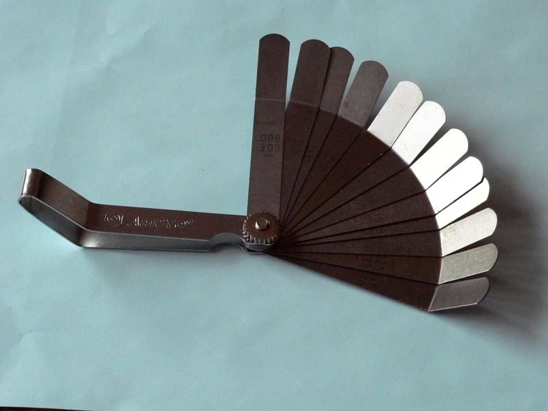
A feeler gauge with a 45 degree bend in each tape makes reaching between the cam and lifter in the the engine head easy. However, the 45 degree gauges usually do not contain a large selection of blades. Most of the blades in the 45 degree feeler gauge pictured above are too big to be of any use in checking valve clearance on a motorcycle.


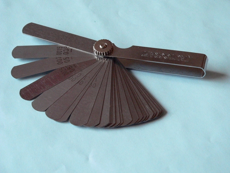
The flat feeler usually has more blades and it usually has mostly the thinner blades which are the most useful in measuring valve clearances. It is possible to reach the flat blades to the space between the cam and lifter because the smaller blades below .012” bend easily and spring back into shape.


Micrometer
A standard unit micrometer with a flat anvil can be used but it will be necessary to convert the measurements to metric when measuring shim thicknesses. It will be easier to use a micrometer that is marked in millimeter decimals.


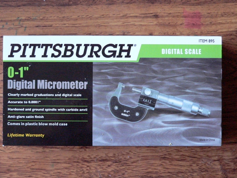
I purchased the micrometer shown above at Harbor Freight for $17 and it has proven to be very accurate checked against the tapes in my feeler gauges. For a few dollars more, Harbor Freight has a Pittsburg micrometer that has an LCD digital display that will show inch decimals or millimeters.

Valve Clearance Measurement
Do First:
Remove Fuel Tank
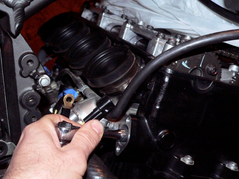
Remove Throttle Body Assembly (optional but recommended)
Remove Engine Heat Insulator Rubber Plate
Remove Engine Head Cover
Remove Crankshaft Sensor Cover and Position Crankshaft at Top Dead Center, Cylinder #1 (See Crankshaft Sensor, steps 1-3 also steps 1-3 below)


Tools:
17mm socket
valve clearance feeler gauge
diagram/record sheet for valve clearances


1. Use a 17mm socket to align the 1.4 T and the 2.3 T marks up with the marks on the edge of the engine case (Photo A). If you turn the rotor past the point where the marks line up, do not turn the wheel backward (counterclockwise). Instead, continue turning the motor clockwise 360 degrees to come back to where the marks on the case and the wheel line up.

Photo A
TDC #1
timing wheel, TDC marks lined up with engine case marks?


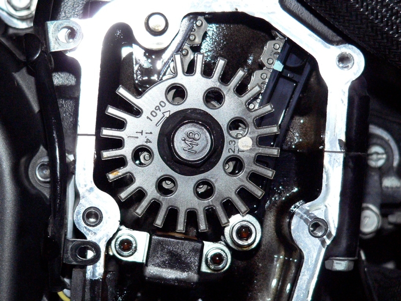
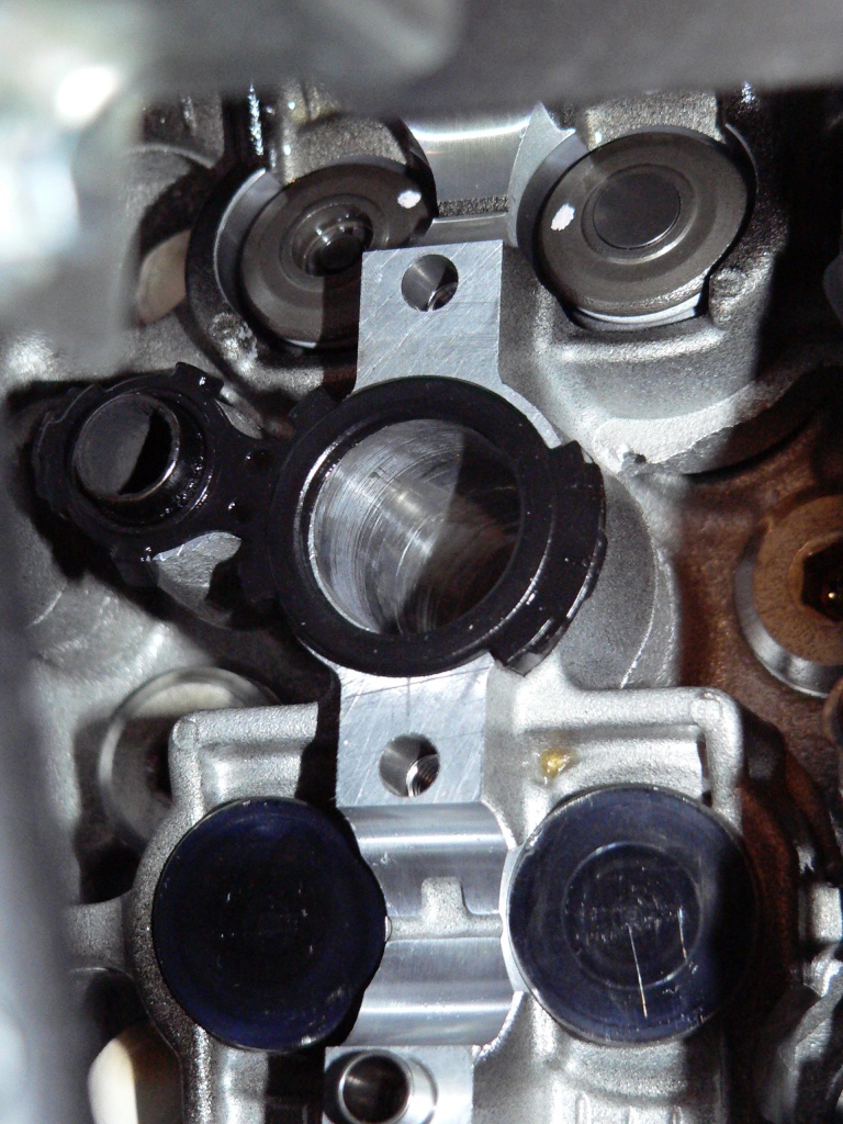
2. Inspect the cams on the extreme left (clutch lever) side of the cam shafts. The cam lobes should be pointed away from one another.

Photo B
TDC #1
cam lobes on extreme left, point away from one another

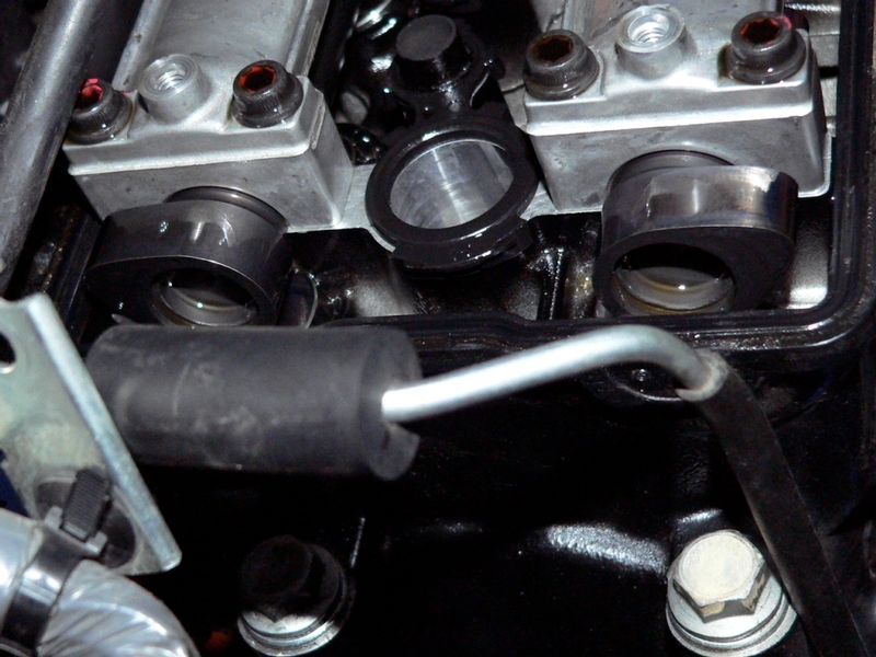
The cam lobes on the extreme right (brake lever side) should be pointed toward one another.

Photo C
TDC #1
cam lobes on extreme right point toward one another

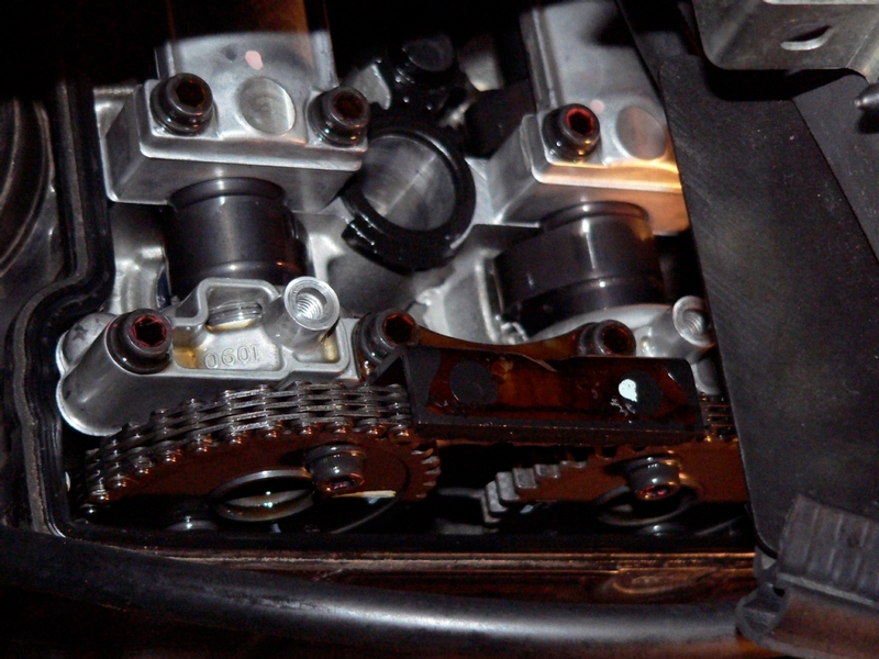
If the the timing wheel has been positioned as shown in photo A but the cam lobes are pointed in the opposite directions that are shown in Photo B and Photo C, cylinder #4 is at TDC of the compression stroke. Turn the timing wheel 360 degrees. That will put cylinder #1 at TDC of the compression stroke and the cam lobes and timing sprockets will be positioned as described and shown in photo B and photo C.


3. When Cylinder #1 is positioned at TDC of the end of the compression stroke, the timing sprockets will appear as shown in Photo D. The engine is now positioned properly to check the valve clearances of half of the valves.

Photo D
Cylinder #1 TDC
Two marks to the inside of the sprockets are in line with the top of the engine case. No other marks are visible.


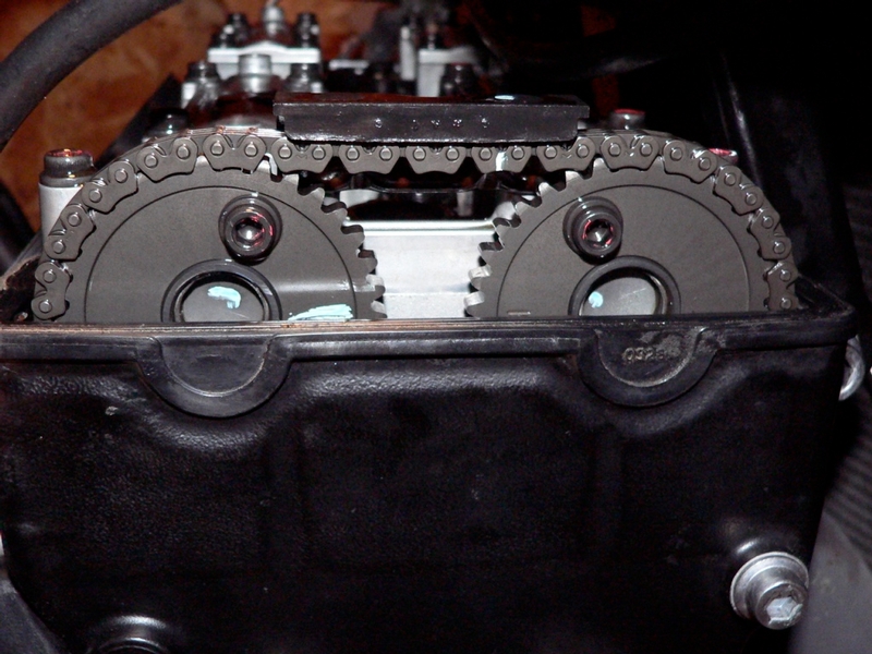
4. The valves marked solid black on the diagram below may have their clearance checked with cylinder #1 placed at TDC of the end of the compression stroke. These are all 4 valves of cylinder #1, both exhaust valves of cylinder #2 and both inlet valves of cylinder #3.


DIAGRAM 1 valve clearances to measure with Cylinder #1 at TDCCS


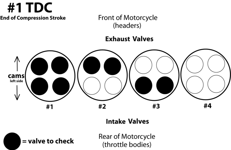
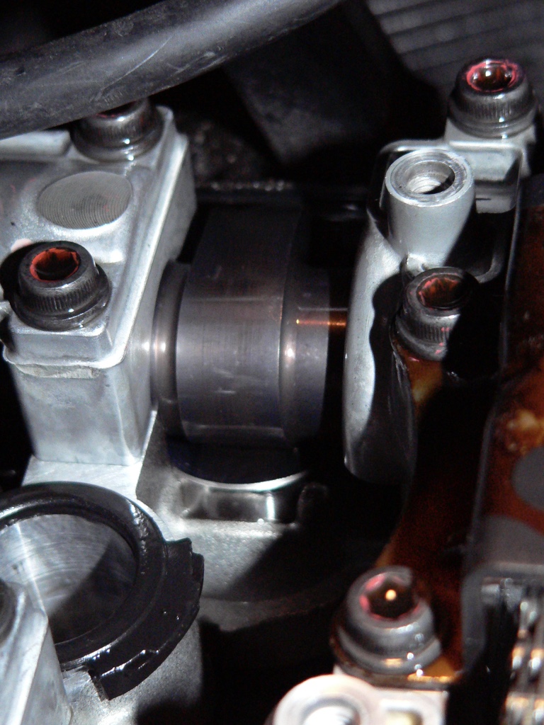
This photo shows a cam with a lifter (the small chromed cylinder) below it. The tiny space between the top of the lifter and the cam is what is measured with the feeler gauge.


5. The feeler gauge is inserted between the lifter and the cam.

spec valve clearance, inlet valves: .15 mm ~ .20 mm
spec valve clearance, exhaust valves: .22 mm ~ .27 mm

If the tape does not slide right in without resistance, it is too large. Try the next smaller tape. If the tape does fit, try the next larger one in the set to see if it will fit. Repeat the process until the largest tape in the set that fits without resistance is determined. Use the same procedure to measure all the valves indicated in the diagram. Do not force tapes between cams and lifters or the surface will become scratched.


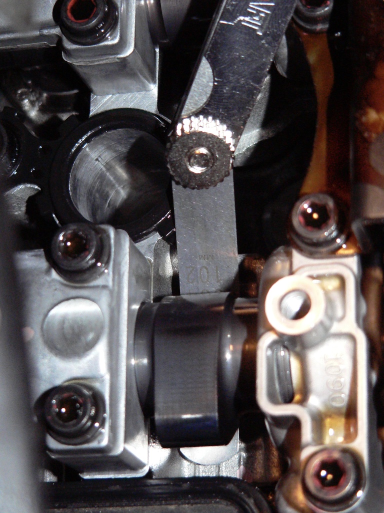
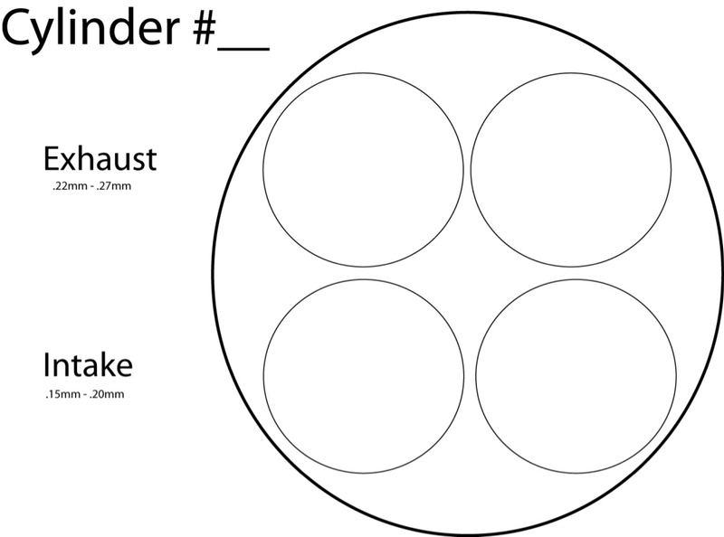
6. Record the valve clearance measured for each cylinder. Copy diagram 2 below (you will need one copy for each cylinder) or draw some diagrams similar to it. Keep the valve clearances and related information written in the proper positions and kept organized for future reference.

DIAGRAM 2 valve clearance measurement record


7. When all of the clearances with cylinder #1 at TDC have been measured and recorded, turn the timing rotor 360 degrees (see Crankshaft Sensor, steps 3-4) so that cylinder #4 will now be at TDC of the end of the compression stroke.

Photo E
Cylinder #4 TDC
The cam lobes on the extreme left will be pointed at one another


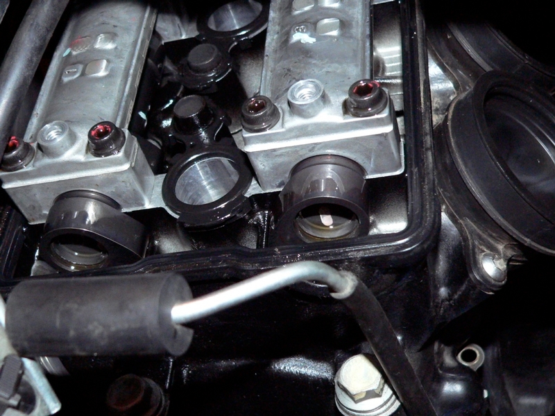
The timing rotor will be at the same position as it was in step 3 (the 1. 4 mark aligned with the mark on the edge of the engine case) However, the cams on the far left side of the motor will now be turned toward one another.


Photo F
Cylinder #4 TDC
The cam lobes on the far right side of the motor will be turned away from one another.
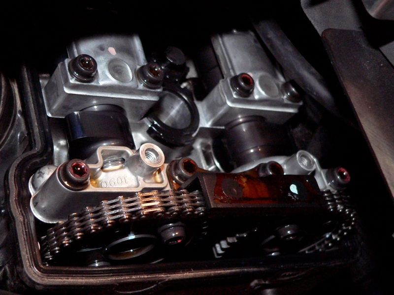
Photo G
Cylinder #4 TDC, Camshaft Sprockets
There is a mark parallel to the top edge of the engine case on the outside of each wheel. Also a mark on each sprocket approximately 45 degrees to the top edge of the engine case.


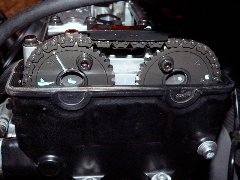
8. When cylinder #4 is at TDC of the compression stroke, the clearances for the valves shown in the diagram below may be measured and recorded as described in step 4. Measure the clearances of the two inlet valves of cylinder #2, the two exhaust valves of cylinder #3 and all four valves of cylinder #4. Use the same diagram (diagram 2) to record these clearances as was used to record the #1 TDC clearances.

DIAGRAM 3 valve clearances to measure with Cylinder #4 at TDCCS


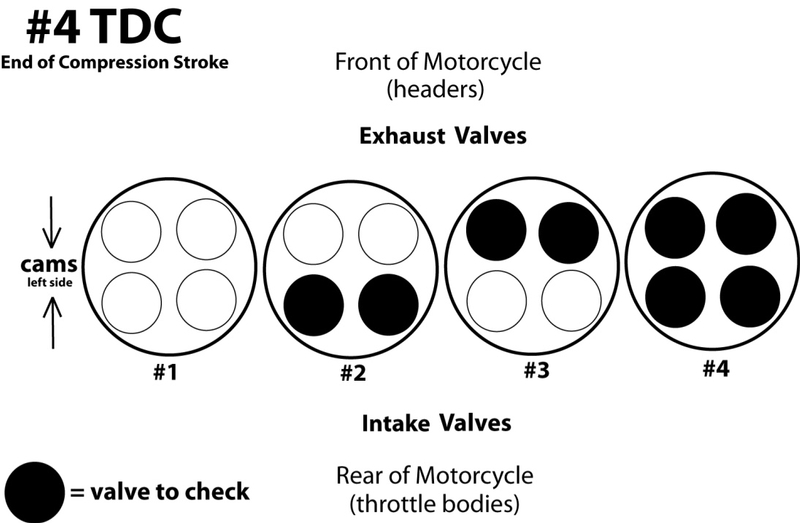
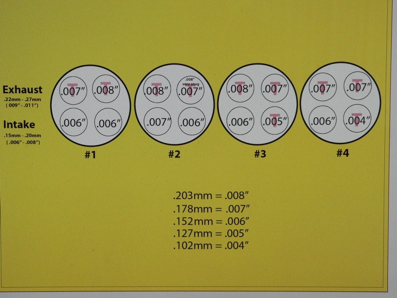
DIAGRAM 4 Valve Clearances Measured Before Adjustment


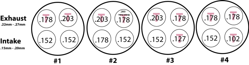
Above are the clearances recorded for my bike, checked past due at 29,000 miles. The clearances are expressed in millimeters. T indicates a tight clearance that should be adjusted.

DIAGRAM 5 Valve Clearances Expressed in Inch Decimals


This is the same diagram as Diagram 4 except it is expressed in inch decimals. As you can see, the inch decimals on the feeler gauge are in round numbers which make comparing clearances easier to conceptualize and compare.


9. If any clearances require adjusting proceed with the following steps in order. If all clearances are in spec, skip to step 22 .

Valve Clearance Adjustment
Do First:
Do Valve Clearance Measurement, steps 1-8 above.
Remove the Camshafts

Tools:
magnet tool with flexible shaft
painters tape
8 mm socket
rag
screwdriver
drip pan
17 mm socket
gap thickness feeler gauge
micrometer

Materials and parts price
(qty according to amount needed) 9.48mm OD replacement shims
(Kawasaki part # varies according to shim thickness).................................10.12
Hot Cams shims are sold in refill packs of 3 from Denis Kirk and are much cheaper.

OEM replacement engine head cover gasket
(Kawasaki part # 11061-0738)...................................................................$33.20

(1)OEM sealant - Three Bond liquid gasket,
(Kawasaki Part # TB1216B: 92104-1064 )...................................................64.00

or GM Engine Sealant (Hub Recommended and much cheaper)

OEM head hole gaskets (Kawasaki part # 11061-0196) .............................6.92

(6)OEM head cover bolt washers - optional to replace................................. 3.82
(Kawasaki part #92055-0143)

(1 liter) A couple ounces of your usual engine oil...........................................5.00

Kawaski Parts House is one online source of OEM parts


Bike Bandit is another

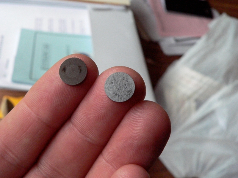
10. Use a magnet tool with flexible shaft to remove each lifter. The magnet will both pull the lifter up and usually cause the shim to stick inside of the lifter. Take caution not to drop a shim in the head or timing chain tunnel. Place a piece of painters tape on each lifter and mark it for reinstallation. Indicate the lifter’s cylinder number, left or right side and exhaust or inlet valve. Fold a piece of painters tape over each shim and mark it with the same information. Mark each lifter and its shim as soon as it is removed. It is crucial to avoid inaccurate marking and mismatched parts.


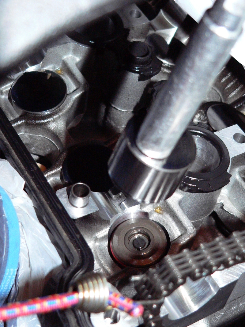
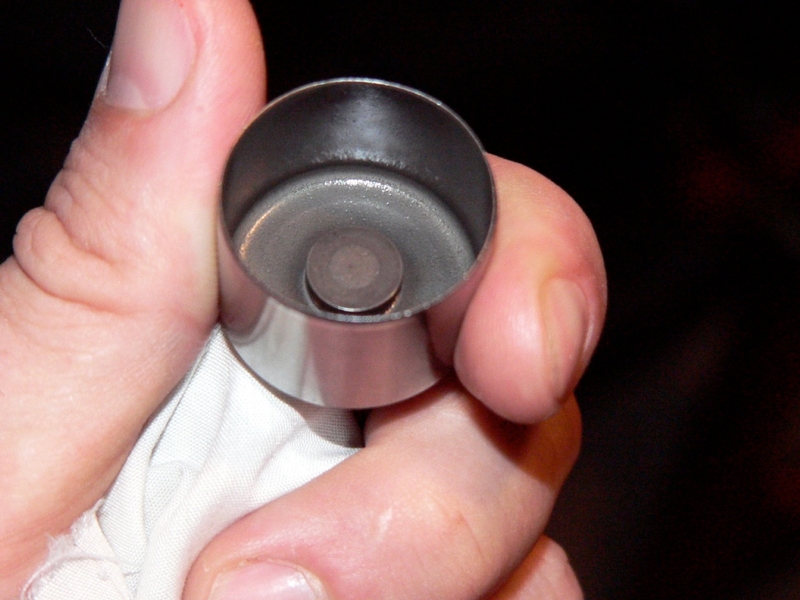
The shim will usually stick to the inside of the lifter. Be sure to mark the shims and the lifters as soon as they are removed so that they may be installed back to the same valve stem.


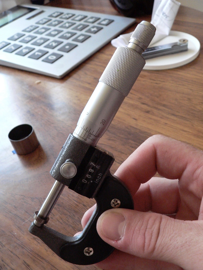
11. Remove the tape label from one shim. Use a micrometer to measure its thickness to the 1/1000”. Record the measurement of the shim thickness. I used the same sheets as those which I had recorded the clearances. Replace the tape label and proceed to measuring the next shim. Do all of the shims one at a time reaffixing the label after measuring to avoid mismatching.


12. The next step is to determine what sized shims will be needed to produce the necessary adjustments to achieve valve clearances that fall within specced parameters. All that need be done is to use the tables below. There is a separate table for inlet valves and exhaust valves copied from the ZX-14 Service Manual. Cross reference the valve shim clearance that was measured with the feeler gauge (in the left vertical column marked “Valve Clearance Measurement”) with the shim thickness that was measured with the micrometer(in the row third from the top marked “Thickness ”). The number that is shown where the two intersect is the size of shim needed to produce an adjustment that will bring the clearance into spec.

Don’t forget, it is sometimes possible to swap over an out of spec shim from one valve in order to produce the proper adjustment in another valve. If you remove a shim that ends up being the right size for another valve clearance, might as well use it for that instead of buying a new one.

Exhaust - Valve Clearance Adjustment Chart

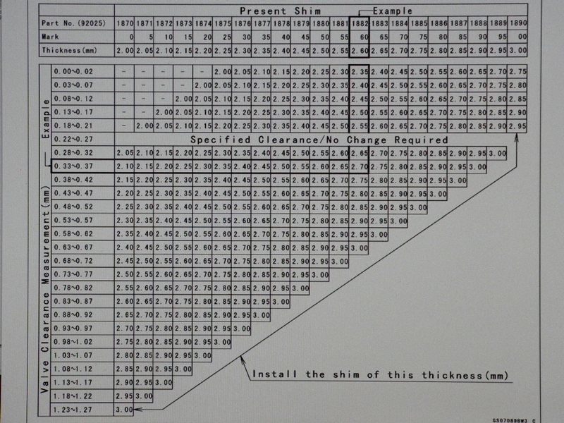
Inlet - Valve Shim Adjustment Chart

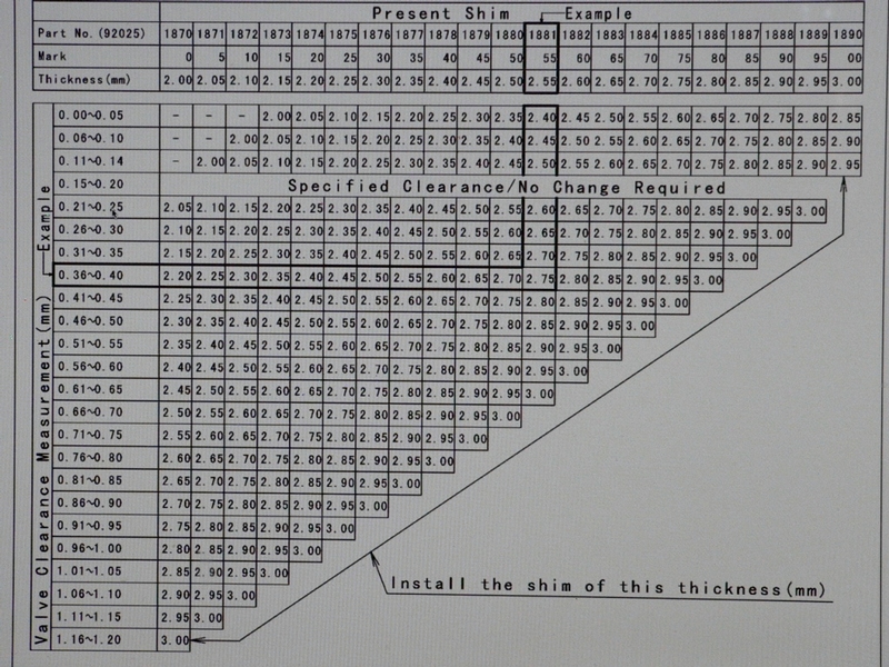
Using the charts above is a simple way of getting your clearances into the specced range (.22mm-27mm for exhaust, .15mm-.20mm for inlet). If you wish to adjust valves with extreme precision for some special purpose then you will need to calculate the ideal shim thickness for each valve clearance you wish to adjust. This is done through a simple sequence of addition and subtraction calculations.

Valve clearance becomes smaller with wear on the valve seat. Normally, the clearance you hope to achieve (ideal clearance) is greater than the clearance you actually have (present clearance). Therefore, you will be subtracting the present clearance from the desired clearance.

Step A
calculate difference between ideal clearance and present clearance

Ideal Valve Clearance (the exact clearance you wish to achieve)
.229mm

minus Present Valve Clearance (as measured by feeler gauge)
.178mm

equals the Difference between the present and the ideal clearance (the amount the valve clearance will need to be adjusted)
.051mm

.229mm
- .178mm
.051mm

Normally valve clearance gets tighter with wear. For this reason, you will be replacing the old shim with a thinner shim so the lifter will not ride as close to the cam. The valve clearance will be adjusted looser (larger). Because you will be using a new shim of less thickness, you will subtract the Difference in step A from the Thickness of the Present Shim to find the Ideal Thickness of the Replacement Shim. This is demonstrate below in Step B.

Step B
calculate the ideal thickness of the shim that will be used to replace the previous shim

The Thickness of the Present Shim 2.565 mm
(as measured with micrometer)

minus the Difference (from Step A) - .051 mm
----------------

equals the Ideal Thickness of the Replacement Shim 2.514 mm


Remember, the thickness you calculate for the replacement shim is “ideal.” All the new shims you order will not be the exact thickness to the hundreth of a millimeter as labeled. You will want to measure them before installing them. The thousandths decimal place will probably not make enough difference to affect precision clearance but the hundreth often does.

Further, it is unlikely that you will find a shim that is exactly the size you need. In that case, it is best to use a shim that will make your clearance larger than minimum spec rather than smaller. The clearance will always get smaller with wear. At some point, the exact clearance you were aiming to adjust to will happen through ordinary wear.

If for some reason you wish to reduce the valve clearance, you will want to replace the previous shim with a thicker one. You will need to add the Thickness of the Present Shim to the Difference in step B.

As I understand it, adjusting shims to create a clearance larger than maximum spec is unsafe. Extremely loose valve clearance could allow the shim to fly out of place which would result in catastrophic engine failure.


* Last updated by: Rook on 6/25/2018 @ 11:29 PM *


'08 MIDNIGHT SAPPHIRE BLUE Now Deceased

Link | Top | Bottom

Rook


Rook's Gravatar

Joined: 03/28/09

Posts: 20577

RE: Valve Clearance Check and Adjustment
01/13/12 2:18 AM

13. Order the shims you will need. If the charts were used to determine the correct shim size, simply order the size shown in the chart. If you are calculating your own shim size, you will need to order a shim which is as close as possible to the exact size you need. If you are unable to find the exact size you need, you are best to order the next thinner shim so that the clearance will be a bit larger than perfect rather than a bit smaller.

Hot Cams shims are much less expensive than OEM Kawasaki shims. However, the thickness of Hot Cams shims may not be quite precise to .01 mm. OEM shims seemed to be precise to .001mm. OEM shims are also made in finer increments of .025mm where other shims are made in .05mm increments. Hot Cams shims will probably be just fine if you are adjusting your clearances to the middle of the spec range. I definitely recommend using OEM shims if you are adjusting close to tolerances.


Valve shims will have their thickness printed or stamped on one side. The ZX-14 Service Manual suggests that the shims be installed with the number side facing up toward the lifter. I also have been told the number side of the shim should face downward as the lifters will rotate better on the smooth side. If the numbers face downward, the numbers will have a smaller contact area and be more likely to remain readable. Kawasaki shim numbers are large. With “Hot Cams” shims, the number is directly in the center and will probably wear off no matter which way the shim is placed. I do not think it matters much which side faces up when installing shims. I found some of the numbers facing up and others down when removing the factory installed shims.


14. Measure the replacement shims with a micrometer to check their size. If the shims are not sized exactly as labeled, you should do some last minute calculations (Step 10 A and B, above) to determine if they will still work. Mark the replacement shims according to which valve it will be installed to.


15. Install any shims that will be swapped from one valve to another. Install the new replacement shims and also the original shims that were still within spec. Install the shims to the valve retainer and lube each one with a drop of oil.


16. Lube each lifter with oil and install it to the valve it was marked to.


The lifters have been reinstalled on the two valves toward the bottom of the picture. The valve on the top right has the shim placed in the top of the valve guide. The top left valve guide has no shim installed.


17. Install the camshafts. Install the camshaft caps using only 60 in lbs of torque on the camshaft cap bolts. (Camshaft Removal/Installation, steps 9-14)


18. The engine remains where it was last positioned at #4 TDC. Recheck all valve clearances for #4 TDC (see diagram 3 in step 7 of this tutorial) using the feeler gauge. If any of the clearances are still out of spec, make a note of which ones they were and what the clearance was after the adjustment.


19. Remove the plastic dust covers from the throttle body holders so that it will not get sucked into the intakes when the motor is turned. Also remove the plastic cover from the cam chain tensioner hole. Remove the crankshaft sensor cover (see CRANKSHAFT SENSOR COVER REMOVALsteps 1 and 2). Carefully remove the bungee from the cam chain. Hold the chain to the inlet sprocket so that it will not skip any teeth. The Cam chain and the sprockets must remain precisely in time.

20. Hold pressure against the camshaft chain guide with the blunt end of a tool such as a 1/4 in drive ratchet handle. It is crucial that tension be maintained on the camshaft chain while the engine is being repositioned. If tension is not maintained the cam chain will jump teeth on the inlet sprocket and become out of time. Use a 17mm socket to turn the timing rotor center nut to Cylinder #1 TDC (see step 1 and 2 of Crankshaft Positioning [url=http://www.zx14ninjaforum.com/messages.cfm?threadid=A0256B66-D56B-84E2-11E51E6DFBC30651]


Reach through the Cam Chain Tensioner hole with a blunt tool such as the back of a 1/4 inch drive ratchet handle. Hold tension on the Camshaft Chain guide while turning the Crankshaft with the center nut of the Timing Rotor.


21. Check all valve clearances for #1 TDC (see steps 4 and 5 and diagram 1 of this tutorial) with a feeler gauge. If any valve clearances for TDC #1 are out of spec, note which valves were out of spec and what the clearance was. If any valve clearances were found to be out of spec after all 16 valves were checked, it will be necessary to remove the camshaft caps and camshafts (see Camshaft Removal, steps 2 through 7).

Remove the lifters (step 10 of this tutorial). Repeat steps 12 through 18 of this tutorial to install a different sized shim for each valve clearance that requires readjustment and check the clearances again.


22. When all clearances are acceptable, torque the camshaft cap bolts (see Camshaft Removal, step 12).


Install Crankshaft Sensor Cover (Crankshaft Sensor, steps 5-8)

Install Engine Head Cover see Cylinder Head Cover, steps 3-6

Install Engine Heat Insulator Rubber Plate

Install Throttle Body Assembly

Install Fuel Tank

Install Fairings


* Last updated by: Rook on 10/9/2017 @ 7:43 PM *


'08 MIDNIGHT SAPPHIRE BLUE Now Deceased

Link | Top | Bottom

Somefun


Somefun's Gravatar

Location: Connecticut

Joined: 09/09/10

Posts: 902

RE: Valve Clearance Check and Adjustment
02/05/12 9:09 AM

Rook I'm in the process of doing my valves. With 22,000 miles on her they were all on the tight side for sure. Most all at the edge of the tight side limit. I have gone through the ext and intake chart and it looks like I need mostly 250mm intake shims and 240 exhaust shims. How ever this is according to the chart. If I do the math the exhaust should be more like 250mm my questions is doing it by the math does that make it on the tight side or loose side? Or right in the middle? I'm not sure if I should go with the Kawasaki chart says or the math? If I went the math it would make the exhaust side tighter and looser should be better?? What do you think? Also is it safe to use some Kawasaki shims and some hot cams? Kaw has some that match my intake number exactly and I was thinking if I went with the math route I’d use some OEM shims.


2023 Ram TRX 09 ZX14 Monster Top Speed 203.47 2015 H2 2023 Ducati V4R 2023 KTM890 Adventure R 2022 KTM Super Duke Evo R 2021 Ducati Street Fighter V4S 2018 Husqvarna FS450 2023 Husqvarva TE300I Kawasaki Z125 with a 2023 KX450 motor with BST wheels

Link | Top | Bottom

Rook


Rook's Gravatar

Joined: 03/28/09

Posts: 20577

RE: Valve Clearance Check and Adjustment
02/05/12 6:52 PM

With 22,000 miles on her they were all on the tight side for sure. Most all at the edge of the tight side limit.

OMG, I shoulda copied my PM response to you and pasted here.

The most important points:

You have PERFECT clearance now so leave it. Adjust it looser after several K more miles.

In the math approach, you pick the clearance you want to shoot for. You want loose, you shoot for loose. Tight? you shoot for tight.

ME:

Step A
calculate difference between ideal clearance and present clearance
Ideal Valve Clearance .229mm
(the exact clearance you wish to achieve)

Ideal clearance is the clearance that you consider to be good for your puposes. Generrally that be right in the middle of the sec range. Tight if you are racing, Loose if you don't want to go through this crap again for a long time----ALWAYS< ALWAYS ALWYAS stay in the spec range b no matter what you consider "ideal." MUST be in spec. IF it gets a bit tighter than minimum spec, I doubt that would cause a bit of harm----not for a long time but you don't want to mess with being out of spec. BAD things could happen, why tepmt fate?


&#x27;08 MIDNIGHT SAPPHIRE BLUE Now Deceased

Link | Top | Bottom

Rook


Rook's Gravatar

Joined: 03/28/09

Posts: 20577

RE: Valve Clearance Check and Adjustment
02/05/12 6:55 PM

...and all that matters is that "in spec" feeler gauge tape slips through to tell you that your clearance is good. Measure until you're blue in the face but the tape is the deciding factor.

She no slide, you do over.

(well, I left one of my valves a wee bit tighter than spec. It was loosened up a bit after the adjustment but not enough. Better than it was before so I called it quits). That's what I get for shooting for minimum spec. Next time I will go for a bit looser. Middle, probably.


* Last updated by: Rook on 2/5/2012 @ 6:57 PM *


&#x27;08 MIDNIGHT SAPPHIRE BLUE Now Deceased

Link | Top | Bottom

Rook


Rook's Gravatar

Joined: 03/28/09

Posts: 20577

RE: Valve Clearance Check and Adjustment
02/05/12 6:59 PM

aint that cam chain tensioner a bitch?


&#x27;08 MIDNIGHT SAPPHIRE BLUE Now Deceased

Link | Top | Bottom

ubertourer


ubertourer's Gravatar

Location: norfolk england

Joined: 06/13/12

Posts: 15

RE: Valve Clearance Check and Adjustment
06/13/12 10:36 AM

need to know the tightening sequence of the camshaft cap bolts. the manual i have tells you to do a certain sequence from the first to the last bolt but the diagram is missing the number sequence for the bolts. anyone got a diagram they can post on here for me.


no replacement for displacement

Link | Top | Bottom

Rook


Rook's Gravatar

Joined: 03/28/09

Posts: 20577

RE: Valve Clearance Check and Adjustment
06/18/12 11:43 PM

^^^^I adressed that. See the "Remove the Camshafts" link immediately following step 9 in this tutorial.

OR-- Here is the url: CLICK>>

Go to step 14. There is a camshaft cap bolt torque sequence diagram right below it.

Great question. You are right, the early ZX-14 SM did not provide the diagram they referred to in the text. I believe I got the diagram from the 2010 SM which was updated with the proper diagram..


* Last updated by: Rook on 6/19/2012 @ 7:22 AM *


&#x27;08 MIDNIGHT SAPPHIRE BLUE Now Deceased

Link | Top | Bottom

Graeme


Joined: 01/21/13

Posts: 1

RE: Valve Clearance Check and Adjustment
01/24/13 2:20 AM

Rook,
What an excellent description of valve clearance check. I thought I may be able to save ZX14 owners a lot of time and stress with some further suggestions. Having just completed a valve adjustment I believe you do not have to remove any of the induction system or fuel tank and still be able to remove the engine cover quite easily. I did not remove any of the fuel injection but I did remove the ram tubes and the fuel line to the injection system which I wish I had not done because reconnecting the fuel line was quite tricky. I had already lifted the fuel tank and found it quite difficult to separate the connectors under the tank so I left them connected and just turned the fuel tank at 90 degrees to the frame and sat it on the frame on a towel and the rubber bungs on the tank. I believe I should have left the fuel tank in place and not touched the induction system at all.
The rubber engine cover is a pain as it is difficult to disconnect anything or undo bolts with it in place so I just cut it off completely which made everything a lot easier to see and manage.
All other steps to valve clearance check are pretty much as per the workshop manual so after disconnecting everything you can easily lift the engine cover out to the right hand side. The only other tricky thing was figuring out how to set the cam chain tensioner which is not very well explained in the workshp manual. The trick is to hold it down on a block of wood, squeeze the rear circlip together and push the piston back into the body until the outer circlip lines up with the outer groove on the piston and pull the end of the outer circlip out towards the centre of the tensioner body and it will lock into place.
The manual instructs you to hit the end of the piston with a screwdriver after you have installed it but I think you will find when you install it , it will unlock as soon as it touches the cam slider.
The only other annoying thing I found was disconnecting the throttle cables from the throttle bodies which you really have to do to get access to the engine cover. There are two phillips head screws holding the cables on and no matter how much I tried with various size screwdrivers I could not move them. My solution was lucky for me as I have an air wrench with a philips head attachment and one little squirt undid them without any damage to the screws.
Just for information all the exhaust valves needed adjusting down by .05mm and one inlet by .05mm.
Hope this helps

Link | Top | Bottom

Rook


Rook's Gravatar

Joined: 03/28/09

Posts: 20577

RE: Valve Clearance Check and Adjustment
01/24/13 8:55 AM

Thanks Graeme

I believe you do not have to remove any of the induction system or fuel tank and still be able to remove the engine cover quite easily

The T-bodies can stay but you cannot remove the rubber blanket from the motor without removing the t-bodies. ...thwen again, I believe someone else has already pointed out in an earlier comment here that the rubber blanket does not need to come off to remove the head cover either.

AFA the fuel tank is concerned, that is a must IF one intends to remove the t-bodies.

Now that I have the rubber blanket, and PAIR removed, it is a lot less cluttered under there. I'd try to remove the cover without taking out the t-bodies. I think the SM recommends t-bodies be removed.

Yes the connectors on the fuel line are hard to figure out how to unlock. Once it is understood that the orange block simply needs to slide outward, unlocking is easy. I hade 0 problems reconnecting the fuel lines. Just snap the orand block back and push and pull a few time to be sure the line is fastened.

The only other tricky thing was figuring out how to set the cam chain tensioner which is not very well explained in the workshp manual. The trick is to hold it down on a block of wood, squeeze the rear circlip together and push the piston back into the body until the outer circlip lines up with the outer groove on the piston and pull the end of the outer circlip out towards the centre of the tensioner body and it will lock into place.
I discovered the same trick. Arnold Schwarzenegger couldn't press that piston back in there. You need to push the CCT down on something to force the piston in as you have described. I believe there is a link to Cam Chain Tensioner Installation in this tutorial. I have pics and verbal description.

The manual instructs you to hit the end of the piston with a screwdriver after you have installed it but I think you will find when you install it , it will unlock as soon as it touches the cam slider.

Nope, Mine did not but if yours did, you saved a step. I had to push a screwdriver in the cam chain tunnel and work it against the cam chain like plunging a toilet. A few pushes and I heard and felt the piston pop.

There are two phillips head screws holding the cables on and no matter how much I tried with various size screwdrivers I could not move them.

I too removed the screw and had a hell a time. I used a hot screwdriver. After taking the throttle cables off, I discovered there is a simple spring clip that holds the cables to the t-bodies. All you need to do is remove the clip. There is a link in this tutorial to throttle bodies removal and a link in that tutorial to throttle cable removal. Shows clear pictures. Next time just take off the clip and the cables come right out.

Step 7 here


* Last updated by: Rook on 1/24/2013 @ 9:03 AM *


&#x27;08 MIDNIGHT SAPPHIRE BLUE Now Deceased

Link | Top | Bottom

KAK


Location:

rockandahardplace

Joined: 02/16/09

Posts: 761

RE: Valve Clearance Check and Adjustment
11/24/13 3:05 PM

Rook, I don't understand why you say valve clearances will always decrease as the valves wear.
My '07 valves were quiet until about 1,000 miles ago. I have 13,000 miles on it. I don't ride it hard. Now I'm hearing a little "ticking" on the right side. I assume it's only one valve but who knows?
The ticking means the clearance has increased at at least one valve. If valve clearances always decrease with wear, why has this noise started?
I've always adjusted the clearances on my '79 GS1000 and I do it correctly. I've had several valves over the years show an increase in clearance.
I'm no expert on this subject and I'm certainly not arguing anything. I just want to understand what's happening in the case of my two bikes. I wish I had the nerve to try adjusting my 14's valves but I may chicken out and try to find a shop with a good reputation instead. I have a reasonable amount of patience and the tools but I admit I'm concerned about disturbing the cam chain and removing the cams. Just never done that before.
I'm finding out the 14 is so much more work than the GS no matter what it is you want to service.

Link | Top | Bottom

Danno


Danno's Gravatar

Location:

Southwestern Illinois

Joined: 12/18/11

Posts: 2142

RE: Valve Clearance Check and Adjustment
11/24/13 6:54 PM

The shims come in .05mm (.002") increments, so if your measured clearance is .05 mm too tight, you have to go to the next smaller shim to open it up that much. If the clearance is at the tight end of the tolerance, adjusting more than one shim size will likely take you over the limit at the other end. I have a Hotcams shim kit, and when I pull a shim and measure it, I should already know by the measured clearance how much (how many sizes) to adjust one way or the other. I put the measured shim back into the appropriate bin for future use and try to keep the kit stocked with at least 3 shims of every size. Sometimes you may need more that three, but shit happens.


'07 CPB Blue; ZGST windscreen with MRA X-screen adjustable spoiler, tube bar adaptor, PC III, ATRE,BMC air filter, modified stock seat with 2nd Look cover,Scorpion Flame Ti slip-ons, Galfer rotors front and rear, braided-stainless lines, C-F 10R front fender, C-F hugger, C-F inner fairing panels, painted foreman's fins with faux C-F inlay, polished rim lips wired for heated gear and accessories, Givi V35 side bags and E41 topcase with SW-Motech qd mounts

Link | Top | Bottom

KoflaOlivieri


KoflaOlivieri's Gravatar

Location:

Philadelphia, PA

Joined: 02/17/12

Posts: 1805

RE: Valve Clearance Check and Adjustment
11/24/13 8:33 PM

KAK: Rook, I don't understand why you say valve clearances will always decrease as the valves wear.

Rook: Cause of Valve Clearance Change:
Over time, the adjoining surfaces of the valves and the valve seats wear. This allows the the valve to rest deeper into the valve seat which in turn, allows the tip of the valve stem to slide farther up the guide. The shim at the top of the guide gets pushed higher which pushes the lifter higher. Because the lifter is riding higher, the tiny space (the valve clearance) between the top of the lifter and the cam is reduced.

On older bikes like your 79 Suzuki GS1000 or older Kawasaki's, shims run against the cams, on top of the bucket. Newer bikes shims are placed under the bucket, so they last longer. The weakest link in this case is the valve seat.

Kofla


* Last updated by: KoflaOlivieri on 12/29/2019 @ 6:02 PM *

Link | Top | Bottom

Rook


Rook's Gravatar

Joined: 03/28/09

Posts: 20577

RE: Valve Clearance Check and Adjustment
11/24/13 8:45 PM

Rook, I don't understand why you say valve clearances will always decrease as the valves wear.

In short, engine wear causes there to be less metal. Less metal does NOT always equate to MORE air between your parts, not in all situations.

"Cause of Valve Clearance Change
Over time, the adjoining surfaces of the valves and the valve seats wear. This allows the the valve to rest deeper into the valve seat which in turn, allows the tip of the valve stem to slide farther up the guide. The shim at the top of the guide gets pushed higher which pushes the lifter higher. Because the lifter is riding higher, the tiny space (the valve clearance) between the top of the lifter and the cam is reduced. There are different optimum clearances for a few different types of engine applications. Some are smaller (tighter) than others. If the valve clearance is insufficient, the valves will eventually burn from having too close of contact between parts or parts will impact. Catastrophic engine failure would be the result in either case."

Go back up to the top of this page to view the fourth diagram in the tutorial. It is the one that has the blue egg shapes marked A and B representing cams. The copy I have quoted right above here in this reply accompanies that diagram. It will become clear why valve wear can ONLY cause valve clearances to decrease (become tighter).

If you ever had one get looser....beats the crap outta me? I suppose it could be a mistake in recording or measuring or perhaps if you did one measurement in the dead of winter and the other on a 100F day in mid summer??? That might cause clearances to vary a couple 100th of and inch or so. ...I guess? Or maybe you had the motor positioned a few degress off of TDC one of the times you measured the clearance?? Wish i had done this more so I could offer more sure advise. Truth is KAK, you have done this a lot more than I have. Only done one valve clearance check in my life and this was it. So look at me, talkin' like some kind of expert or something! ha!

My '07 valves were quiet until about 1,000 miles ago. I have 13,000 miles on it. I don't ride it hard. Now I'm hearing a little "ticking" on the right side. I assume it's only one valve but who knows?

Sure that little ticking is not you Cam Chain Tensioner?

I'm no expert on this subject

Me neither, bro. But now I know a little more than the average guy.

I wish I had the nerve to try adjusting my 14's valves

You should be able to check them without too much trouble. Only thing is you may need to deal with the problem of oil leakage from the head cover after you take that off. Install new gasket and ringOs. BE SURE you don't overdo the torque on the head cover bolts! Accurate torque wrench....calibrated.

....course if you are going to check them, no point in putting the whole shebang back together to take it to a good mech for the adjustment.

Removing the cams is not a lot more complicated than removing the head cover. Just follow the tips in my tutorials that tell you how to NOT get your motor out of time. That is the real risk in doing this yourself. The cam chain is a part of that but no big deal as long as you keep it bungied as shown in my tutorials that I have linked here. Measuring shims with the mic is also something that you need to be very careful about. Take notes, use my diagrams to keep data, draw your own diagrams....do what you need to do to get the measurements right. ...and if they are wrong, be prepared to tear the camshafts back out and make the proper adjustments. I almost had to do that.

I wish I had the nerve to try adjusting my 14's valves but I may chicken out and try to find a shop with a good reputation instead.

Nothing in the world wrong with that. If you want to make sure their reputation is worth a darn, tell them you want to come in to use the feeler gauge BEFORE the camshafts come out. Then you want to come back to do the feeler gauge test AFTER the adjustment has been completed. Be worth and extra hundred bucks...two hundred< if that is what it takes. This is SO much work to do on your own. $200 is nothin to makwe sure this is right. Good peace of mind is worth every penny.


* Last updated by: Rook on 11/24/2013 @ 8:49 PM *


&#x27;08 MIDNIGHT SAPPHIRE BLUE Now Deceased

Link | Top | Bottom

Hub


Hub's Gravatar

Joined: 02/05/09

Posts: 13708

RE: Valve Clearance Check and Adjustment
11/24/13 9:40 PM

KAK,

When you want an easy way to reinstall the cams, paint a link to a cam tooth. Line the paint marks back up, no need to guess. So at TDC #1 compression, or the cam lobes [toe] are facing the exhaust and intake sides, paint the chain/tooth now. That too means to paint the crank to tooth also. If the cams are out, the chain drops off the crank, there are your 3 safety marks so as not to bend a valve you are a tooth off.

Joe-novice here used to set the valves too tight. My feeler gauges would curl like a ribbon being dragged over a scissor blade. So to find a mechanic that can set valves, look at his feeler gauges. If you can fold the blades back in the shield, they look flat as new, that's how you set valves is to leave a gap so you do not crush the blade to where it drags. That is too tight!

Ask me how I know? I would make them so tight, guess what noise I heard after it warmed up? A ticking noise. So yes, your valves are getting tight. How? The seat has a perfect 45 degree angle, the valve is machined to a 45 degree angle. The pounding of those two against each other, the 45 flattens out, the valve face mushrooms.

The valve face has a gully pounding at this small line around the valve face. If the seat never moves, the valve lash goes big. See how the vavle could drop down over the seat cut in a way? Think if you had carbon build on the valve face? The lash goes big. For the seat to move however, it has to be pounded up into the head where the seat was machined and the seat insert is now moving the valve up the guide, as explained, so the lash goes tight in this direction. Make sense?


* Last updated by: Hub on 11/24/2013 @ 9:43 PM *


Tormenting the motorcycling community one post at a time

Link | Top | Bottom

Rook


Rook's Gravatar

Joined: 03/28/09

Posts: 20577

RE: Valve Clearance Check and Adjustment
11/24/13 9:42 PM

Thanks up there, Kolfa! hahah been a while since i have done this. I had to go back and read my own tutorial. I knew the answer was there somewhere.

Also see I need to keep updating my tutorial illustrations as I reorganize my Photobucket...missing pics is a bit of a problem. Got all the tutorials linked from this one updated with pics....but I am sure there are some others out there that I need to fix up.


&#x27;08 MIDNIGHT SAPPHIRE BLUE Now Deceased

Link | Top | Bottom

Rook


Rook's Gravatar

Joined: 03/28/09

Posts: 20577

RE: Valve Clearance Check and Adjustment
11/24/13 9:57 PM

KAK,
When you want an easy way to reinstall the cams, paint a link to a cam tooth. Line the paint marks back up, no need to guess. So at TDC #1 compression, or the cam lobes [toe] are facing the exhaust and intake sides, paint the chain/tooth now. That too means to paint the crank to tooth also. If the cams are out, the chain drops off the crank, there are your 3 safety marks so as not to bend a valve you are a tooth off.

Great advice from the master.. I took it. See step 6 here click>>Camshaft Removal

One thing, don't hang all your hopes on those paint marks....I mean be very careful how you handle the parts after the marks are made. The paint will slide/crack off the oily parts pretty easy then you are more or less screwed unless Hub has some sort of magic trick he can share with you. Also, if for any reason you turn the crankshaft after the paint marks were painted, the marks are no longer of any use. The same three paint marks will not align in proper engine time the next revolution....you would have to ask Hub that one...I don't recall if I had to deal with that or if I just brought it up hypathetically ....but it is something like your drive chain and sprockets having the same tooth line up to the same link every 60 revs....not each rev as most people ume.


&#x27;08 MIDNIGHT SAPPHIRE BLUE Now Deceased

Link | Top | Bottom

KoflaOlivieri


KoflaOlivieri's Gravatar

Location:

Philadelphia, PA

Joined: 02/17/12

Posts: 1805

RE: Valve Clearance Check and Adjustment
11/24/13 10:01 PM

Thanks up there, Kolfa! hahah been a while since i have done this. I had to go back and read my own tutorial. I knew the answer was there somewhere.

Also see I need to keep updating my tutorial illustrations as I reorganize my Photobucket...missing pics is a bit of a problem.

Rook, we have to thank you for taking the time to put all of these excellent tutorials together, this is a lot of work. I tried to find a double overhead cam valve train diagram to illustrate what you explained, but was unable to find any.

Kofla


* Last updated by: KoflaOlivieri on 12/29/2019 @ 6:03 PM *

Link | Top | Bottom

Rook


Rook's Gravatar

Joined: 03/28/09

Posts: 20577

RE: Valve Clearance Check and Adjustment
11/24/13 11:12 PM

My pleasure. Just about a week ago, I had a member PM me asking to use parts of the tutorial to create a general valve clearance adjustment how to for their site. Seems like a high performance shop. They found the tutorial by searching. It's cool to be Googlable! Andy Warhol was right. you know, the 15 minutes of fame?


&#x27;08 MIDNIGHT SAPPHIRE BLUE Now Deceased

Link | Top | Bottom

Danno


Danno's Gravatar

Location:

Southwestern Illinois

Joined: 12/18/11

Posts: 2142

RE: Valve Clearance Check and Adjustment
11/25/13 5:00 AM

Aligning the timing mark on the ignition wheel and then the marks on the cam sprockets with the top of the case makes it pretty easy to get right as long as the crank doesn't move until you get the cam caps buttoned up. It can be a little fiddly getting the second sprocket to the right place on the chain. Make sure the slack in the camchain is on the intake side until you get the tensioner back in and reset (if you keep the automatic tensioner).


'07 CPB Blue; ZGST windscreen with MRA X-screen adjustable spoiler, tube bar adaptor, PC III, ATRE,BMC air filter, modified stock seat with 2nd Look cover,Scorpion Flame Ti slip-ons, Galfer rotors front and rear, braided-stainless lines, C-F 10R front fender, C-F hugger, C-F inner fairing panels, painted foreman's fins with faux C-F inlay, polished rim lips wired for heated gear and accessories, Givi V35 side bags and E41 topcase with SW-Motech qd mounts

Link | Top | Bottom

Nightmare


Nightmare's Gravatar

Location: Okotoks, AB

Joined: 04/07/09

Posts: 602

RE: Valve Clearance Check and Adjustment
11/25/13 9:11 AM

Instead of paint, if you don't have a grease pen, use a black felt permanent marker. I drew 2 lines at different angles on the side of the chain and on the sprocket, line them back up and you're good to go.

As a side note, you can use a marker to mark your final drive chain (rear wheel) when doing maintenance on it to make it easier to figure out where the "start" of the chain is.

If the timing chain skips a tooth or more on the crank the only way I can think of to get it back into alignment with the cams would be to check the angle of the valves relative to the cams, I don't think the clearances would help at a few degrees off TDC, etc. That was my biggest fear when doing this job was messing up that chain, I loved Rook's advice on using the bungee cord to keep the chain tensioned the entire time, that's just brilliant and I wish this how-to was around when I did my first clearance check!

Link | Top | Bottom

Hub


Hub's Gravatar

Joined: 02/05/09

Posts: 13708

RE: Valve Clearance Check and Adjustment
11/25/13 10:01 AM

Magic marker is one, I use that for the rear chain. I still see the mark after all the grease and wiping off of the old grease. I used nail polish when I needed a few colors to watch the ign timing window, but this is thick enough to fall off and contaminate the oil. I use a 'puff paint' they use to add a design on a t-shirt? It hardens up and is green in color. I let that dry on the cam sprocket and link. I then remove it with a razor, because (1) the oil may relase it off the metal? (2) I'm not going to spin the crank over 60 times like lining up the chain link at the rear wheel. So when I again set the valves, all I need to do is turn the crank a few times to line up #1 TDCompression and remark things again.


Tormenting the motorcycling community one post at a time

Link | Top | Bottom

Rook


Rook's Gravatar

Joined: 03/28/09

Posts: 20577

RE: Valve Clearance Check and Adjustment
11/25/13 1:00 PM

I loved Rook's advice on using the bungee cord to keep the chain tensioned the entire time, that's just brilliant

The bungee idea was not of original Rook ingenuity. I don't know where or who (I recall Hub telling me to keep it tight and not let it fall off the crankshaft sprocket) but I saw a pic in an old tutorial of the bungee idea. It is a good idea but marking the teeth on all 3 sprockets would be a wise backup. Smart to do both just in case Newton's Law decides to strike.


&#x27;08 MIDNIGHT SAPPHIRE BLUE Now Deceased

Link | Top | Bottom

Danno


Danno's Gravatar

Location:

Southwestern Illinois

Joined: 12/18/11

Posts: 2142

RE: Valve Clearance Check and Adjustment
11/25/13 3:15 PM

If the timing chain skips a tooth or more on the crank the only way I can think of to get it back into alignment with the cams would be to check the angle of the valves relative to the cams


If the timing mark on the ignition wheel is set and you align the marks on the sprockets with the case split, it's timed right regardless of the chain. The only thing that matters is the relationship between the spark and the valves. The crank could be 180 degrees out and as long as the plug lights in the right part of the suck-squeeze-bang-blow sequence, you're golden. The ignition wheel only goes on one way.


* Last updated by: Danno on 11/25/2013 @ 3:17 PM *


'07 CPB Blue; ZGST windscreen with MRA X-screen adjustable spoiler, tube bar adaptor, PC III, ATRE,BMC air filter, modified stock seat with 2nd Look cover,Scorpion Flame Ti slip-ons, Galfer rotors front and rear, braided-stainless lines, C-F 10R front fender, C-F hugger, C-F inner fairing panels, painted foreman's fins with faux C-F inlay, polished rim lips wired for heated gear and accessories, Givi V35 side bags and E41 topcase with SW-Motech qd mounts

Link | Top | Bottom

Hub


Hub's Gravatar

Joined: 02/05/09

Posts: 13708

RE: Valve Clearance Check and Adjustment
11/25/13 11:34 PM

If you are 180 out = No start. We are sequential fire. It only fires once heading up to TDC meaning.


Tormenting the motorcycling community one post at a time

Link | Top | Bottom


Welcome to zx14ninjaform.com!
 
New Topic Reply
Next Page

Page: 1 2 3

Previous Page

New Post

Please login to post a response.