

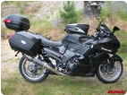
Hubster, I need your assistance. My 2006 ZX-14 is now just over 15 years old and has just under 30,000 miles and has run problem free until today. I went for a ride this morning and noticed my tachometer needle would drop to 0 rpm and then back up to normal rpm, around 5,000 - 6000 rpms on the road I run. I stopped the bike, cycled the switch off and then back on without starting the engine, the tachometer went through the normal startup cycle, maxxed out and then dropped back to zero, so far so good. I started the engine and the tachometer stayed on 0 rpm. Riding home, it briefly began working again and then went to 0 rpm and stayed there. OK, I can run it without a tachometer, so rode it home to do some troubleshooting. Now it get's really bizzare, the coolant temperature LED bars are jumping up and down. The C(Cold LED) bar and the two bars above it illuminate and then the H (Hot) bar and the two LED bars below it illuminate in an alternating fashion when you turn the switch on. This continues as long as the switch is left on. What are the odds of going 15 years with zero issues on this bike and then two separate instrument problems occurring on one ride?
My guess is the two might be related. Your thoughts?
 |
 |
 |
 |
 |
 |
Created on: 10/19/21 01:17 PM
Replies: 91
Kruz

Location:
Joined: 03/16/09
Posts: 6893
Ping Hub ZX-14 Tachometer Problem
10/19/21 1:17 PM
Kruz
Location:
Joined: 03/16/09
Posts: 6893
RE: Ping Hub ZX-14 Tachometer Problem
10/19/21 1:19 PM
I did a search just now on the forum and didn't see anybody ever having a problem like this with their tachometer and coolant temp gauges, maybe I missed it?
Grn14

Location: Montana
Joined: 02/25/09
Posts: 15511
RE: Ping Hub ZX-14 Tachometer Problem
10/19/21 3:38 PM
Heya Kruz!Hope all is well.
I'm not the Hubmiester,but this was mentioned in some threads previously concerning battery issues.Some described the same similar guage symtoms.Have you checked the battery to see if it's holding a charge?Or while riding,what the volts are on the dash?Some also had the fuel level guage flashing f/E.
Glad yer still with us!
* Last updated by: Grn14 on 10/19/2021 @ 3:39 PM *
Rook
Joined: 03/28/09
Posts: 21763
RE: Ping Hub ZX-14 Tachometer Problem
10/19/21 7:09 PM
I had a similar problem crop up with my 08 but it was the speedo that went crazy. I don't recall if anything happened to the tach but the speedo shot up to 90 mph and then it went to zero all while I was doing about 35 mph. Keyed off for a couple hours and it was totally normal when I keyed on. It reset. I believe this was A) water in the inline couplings of the Speedohealer/OEM Speed sensor B) my speed sensor nut slipping.
Come to think of it, it was probably the speed sensor nut slipping. I never evenknew that happened until I changed the sprockets and chain a year ago. Damned good thing it only slipped and didn't continue to loosen. It was hand tight for about 7 years!!
So what would cause your engine RPM sensor to go berzerk?
* Last updated by: Rook on 10/19/2021 @ 7:11 PM *
Hub

Joined: 02/05/09
Posts: 13997
RE: Ping Hub ZX-14 Tachometer Problem
10/19/21 7:50 PM
Sounds more like a connection problem falling out. A failure would be the tach not coming on or self zeroing out on the needle sweep. Like Grn said, where are we 12.8v static wise? Load test wise, volt meter set to 20v and then the leads across the battery, hit the start button and did the battery drop to say 11v and then climb back to say 14.4v [or more] at idle?
The multi-code gathering is what Grn experienced with the crank sensor loosening up and the cam sensor throwing a code. Let's try; key on; kill off; press both mode and trip at the same time and hold down together.
Wait about 5 seconds or less and then write or remember the codes cycling.
The tach inspection is involved. But lettuce try a connection wiggle at the meter connector. That means to let it idle, wiggle the wires at the connector and the connector itself. Watch the tach and if it drops-out and back on, there it is. Not an easy one to diagnose, Kruzer, sans the wiggle... like a few more combos of the same thing: key on, watch the tach needle swing and now wiggle the harness at the meter, That or begin the wiggle before the key goes on. Sporadic needle swinging, there it is sans the deeper involved pin and harness testing.
Because it says; if CAN Com lines show good, crank sensor shows good, replace meter and/or ECU. Looks like you have to have a remote battery, remote wires, a multi-meter, and now since the connector is off the meter, hot these two pins for power, and this pin for ground. Now see if mulit-meter shows such and such ohm resistance at the CAN lines, crank sensor. If you can get a first gen shop manual from online, go to page 16-77, then look at test 18 to run the remote battery setup, then back to test 20 Tach Inspection and read the pin-outs with multi-meter and so on.
And remember, E and its chemical reaction of the green oxy off the copper coated pins is a 14yr growth of that oxidation at the connections. The trick for this is to cut a plastic water bottle, pour vinegar in it and now dip the connector in the vinny and watch for the bubbles to stop. Dip in fresh water to remove the vinny.
Not an easy one, Kruz. The loose pin or corroded pin is the quick and dirty. The book calls the rest. What codes are connected I have no clue. But who is being spit out code wise>>> might not be the tach, but might be causing it to dropout. Might look at it like Grn's code event.
* Last updated by: Hub on 10/19/2021 @ 8:07 PM *
Kruz
Location:
Joined: 03/16/09
Posts: 6893
RE: Ping Hub ZX-14 Tachometer Problem
10/20/21 9:17 AM
Heya Kruz!Hope all is well.
I'm not the Hubmiester,but this was mentioned in some threads previously concerning battery issues.Some described the same similar guage symtoms.Have you checked the battery to see if it's holding a charge?Or while riding,what the volts are on the dash?Some also had the fuel level guage flashing f/E.
Glad yer still with us!
Hi Grn, thanks for your input, bike is starting and running normally, the MFD display shows voltage at 13.0 volts with engine not running, around 13.8-13.9 volts with engine running, I assume that is normal system charging voltage. I have the Firepower Lithium battery installed which explains the higher battery voltage. I'm guessing the battery is fine and is relatively new, changed out maybe two years ago.
When I turn the ignition switch on, the tach and speedometer needles both perform the "sweep" so I assume the tach unit is OK.
Gear position indicator light works normally as does the high beam indicator light, oil pressure light and turn signal indicator lights in the display. Those are direct inputs from the sensors to the meter unit however, i.e. they do not pass through the ECU/CAN system for signal processing. The Speedometer functions normally, again a direct input signal from the speed sensor and not processed by the ECU/CAN.
Here's what indicators are not working in the meter unit and all three of these failed indicators receive their inputs directly from the ECU/CAN communication system. Tachometer does not move when engine is running although it performs the "sweep", coolant temperature flashes the three lower LED bars and then the three upper LED bars alternatively on about a 1 second cycle when ignition switch is turned to "on" position. The red warning light in the display unit does not flash on momentarily when turning the ignition switch to the "on" position. I believe that the red warning light should briefly light up for several seconds when turning the switch to "on" position to verify that it is working but can't remember as I never really paid any attention to it before. If there is anyone listening in that has a Gen 1 ZX-14, maybe they can verify what lights come on momentarily in the display when turning the switch to "on" position.
My thoughts now are either an ECU failure or CAN communication failure to the meter unit, since only the functions controlled directly by the ECU seem to be affected, all independent indicators that bypass the ECU are working perfectly.
* Last updated by: Kruz on 10/20/2021 @ 9:19 AM *
Kruz
Location:
Joined: 03/16/09
Posts: 6893
RE: Ping Hub ZX-14 Tachometer Problem
10/20/21 10:28 AM
Sounds more like a connection problem falling out. A failure would be the tach not coming on or self zeroing out on the needle sweep. Like Grn said, where are we 12.8v static wise? Load test wise, volt meter set to 20v and then the leads across the battery, hit the start button and did the battery drop to say 11v and then climb back to say 14.4v [or more] at idle?Hubster, bike cranks very quickly, performed the starter load test and cranking voltage was still around 13.0 volts on the MFD display but the fuel gauge is flashing alternative Hot and Cold LED bar indications and red warning light is not working when turning the ignition switch to "on", so something is wrong here even before starting the engine. Battery has over 13 volts static before cranking it up, 13.8 volts to 13.9 volts running. I think the battery and charging system is fine
The multi-code gathering is what Grn experienced with the crank sensor loosening up and the cam sensor throwing a code. Let's try; key on; kill off; press both mode and trip at the same time and hold down together.
Wait about 5 seconds or less and then write or remember the codes cycling.OK, tried this just now, ignition switch "on", engine kill switch "off" and pressed Mode and Reset buttons simultaneously, (there is no "trip" button on this bike, so assumed you meant the reset button)No codes were displayed, just the words English and Francais. Not sure how to pull the codes but I'm guessing if I have a CAN communication failure, it cannot pull the codes as they would be stored in the ECU?
The tach inspection is involved. But lettuce try a connection wiggle at the meter connector. That means to let it idle, wiggle the wires at the connector and the connector itself. Watch the tach and if it drops-out and back on, there it is. Not an easy one to diagnose, Kruzer, sans the wiggle... like a few more combos of the same thing: key on, watch the tach needle swing and now wiggle the harness at the meter, That or begin the wiggle before the key goes on. Sporadic needle swinging, there it is sans the deeper involved pin and harness testing.
In total agreement Hub, need to pull the windscreen to gain access to the meter connections and perform the quick and dirty wiggle test and then mate and demate the meter connector several times for the "wipe", had success with this on aircraft avionics before as a quick test. K.I.S.S principle. If the avionics then came "alive", clean the connections. The tachometer came back to life several times on yesterday's ride leading credence to a failed connection somewhere between ECU and meter unit reacting to road bumps. It has been my experience, that ECUs either work or they don't, connections can be tricky and work for awhile and then become either intermittent or just quit outright, can be challenging to troubleshoot.
Because it says; if CAN Com lines show good, crank sensor shows good, replace meter and/or ECU. Looks like you have to have a remote battery, remote wires, a multi-meter, and now since the connector is off the meter, hot these two pins for power, and this pin for ground. Now see if mulit-meter shows such and such ohm resistance at the CAN lines, crank sensor. If you can get a first gen shop manual from online, go to page 16-77, then look at test 18 to run the remote battery setup, then back to test 20 Tach Inspection and read the pin-outs with multi-meter and so on.Yessir, looking at the Service Manual now, very involved with application of power to pins and checking line resistances and ground connections. If it comes down to that and the "quick and dirty" wiggle approach doesn't solve it, it's going to be the "Mother of all troubleshooting battles" hence forth. At that point it might be worth it to consider an aftermarket direct coolant temp gauge and tachometer if such exists anymore. Lettuce remember, this bike is over 15 years old now and probably zero aftermarket support available.
And remember, E and its chemical reaction of the green oxy off the copper coated pins is a 14yr growth of that oxidation at the connections. The trick for this is to cut a plastic water bottle, pour vinegar in it and now dip the connector in the vinny and watch for the bubbles to stop. Dip in fresh water to remove the vinny.
Yessir that will work, I take it you are not a fan of CRC electronic contact cleaner?
Not an easy one, Kruz. The loose pin or corroded pin is the quick and dirty. The book calls the rest. What codes are connected I have no clue. But who is being spit out code wise>>> might not be the tach, but might be causing it to dropout. Might look at it like Grn's code event.
100% in agreement again Hubmeister, based on everything I've seen so far, I'm going to step out on the proverbial limb here and say that I don't think it's a meter unit or ECU failure. "Needle sweep" rules out bad tachometer and all three indicator failures point to a common CAN communication link failure between the "motherboard" and the slave meter unit. My experience with ECUs says they either work or they don't, engine runs great so EFI function is working fine. I think we have a CAN comm link fail to the meter, most likley in a connection somewhere.
Grn14
Location: Montana
Joined: 02/25/09
Posts: 15511
RE: Ping Hub ZX-14 Tachometer Problem
10/20/21 10:52 AM
Turn key on.Wait for sweep.Now press BOTH buttons on the center of the meter unit.HOLD buttons till codes come up.(you may need to release em to show the codes(Can't remember now).If you're getting the language menu,both aren't being pushed in...in my experience.Try again.
Grn14
Location: Montana
Joined: 02/25/09
Posts: 15511
Ping Hub ZX-14 Tachometer Problem
10/20/21 10:56 AM
Didja wash the bike and meter unit recently?And I'd check the terminals on the battery..see if they're clean.Two years on a lithium battery CAN be a long time if not allowed to float charge.Some last way longer...others,not so much.The riding voltage is NOT the battery voltage,course,you know that.
When you installed the battery at first,did you secure the terminal posts while tightening?Hold them with vise grips or something so they wouldn't turn any?If they did turn a bit,the battery could be damaged.And it could be showing up now.The main deal in that is...is the bat holding a charge?You may have already answered that,I might have missed it.
You should remove the battery(IMO),fully charge it,then check later,maybe a day later,or sooner depending.What brand lithium battery is it?
These symptoms sound like a battery issue to me.Weird display behaviors.
Another thing you might try.Charge up the original battery(or another one you might have)and install.See what that does.Go ride.Any previous symptoms?At least you can rule out the battery thing(somewhat)..
It could be as simple as that.Sounds like you've done the right things already.Hope it gets fixed for ya.
Hub knows watt he's talking about.Me?not so much lol.
* Last updated by: Grn14 on 10/20/2021 @ 11:23 AM *
Kruz
Location:
Joined: 03/16/09
Posts: 6893
RE: Ping Hub ZX-14 Tachometer Problem
10/20/21 11:24 AM
Just removed the windscreen and instrument cluster meter connector, performed the wiggle test with engine running and then cleaned the contacts of the connector with CRC electronic contact cleaner and mated/demated the connector several times. That instrument connection has a tight fitting rubber boot and everything looked clean and secure. No changes, no tachometer still and the coolant temp is still going crazy. Grn, I'm not sure about the battery theory, she's showing 13.1 volts at shutdown on the MFD, cranks fast and the charging system appears to be operating fine. I was showing about 13.7 volts on the MFD display while running and it went up to 14.1 volts briefly as she warmed up. I think the MFD voltmeter reads a tad low as I recall. Hubster, please weigh in hear, could I have a bad battery that is not effecting anything else but the instrument display, i.e. cranks quickly and shows normal voltage at shutdown and when charging?
Kruz
Location:
Joined: 03/16/09
Posts: 6893
RE: Ping Hub ZX-14 Tachometer Problem
10/20/21 12:05 PM
Can anyone decode this from the Japenglish, Chapter 16-65 from the 2006 ZX-14 Service Manual?
NOTE:
1. The flashings of the three segments for the water temperature gauge and fuel level gauge do not failure of the
meter unit.
2. Currently, for the meter is disconnected from the main
harness each flashing occur.
3. The flashing of water temperature gauge is communication error to the ECU.
4. The flashing of the fuel level gauge is open or short of
the fuel reserve switch.
5. Normally, each flashing disappears when the meter unit
is connected to main harness.
The flashings of the three segments for the water temperature gauge and fuel level gauge do not failure of the
meter unit.
This statement in particular has me puzzled as the three segments of my water temperature gauge are flashing but the wording is impossible to comprehend. What does "do not failure of the meter unit" mean?
This is a bench test and the meter is disconnected from the main harness so there is no CAN communication. If I am reading this correctly, the flashing three segments I am getting denote communication error to the ECU.
* Last updated by: Kruz on 10/20/2021 @ 12:14 PM *
Kruz
Location:
Joined: 03/16/09
Posts: 6893
RE: Ping Hub ZX-14 Tachometer Problem
10/20/21 7:22 PM
Turn key on.Wait for sweep.Now press BOTH buttons on the center of the meter unit.HOLD buttons till codes come up.(you may need to release em to show the codes(Can't remember now).If you're getting the language menu,both aren't being pushed in...in my experience.Try again.
Apparently the codes are EFI and Ignition codes only and I apparently don't have a code displayed. I tried it several times following the Service Manual Instructions and no codes were displayed.
Grn14
Location: Montana
Joined: 02/25/09
Posts: 15511
RE: Ping Hub ZX-14 Tachometer Problem
10/20/21 10:04 PM
"gauge do not failure of the
meter unit"...meaning:Those displays flashing mean the meter unit is fine.
"The flashing of water temperature gauge is communication error to the ECU.
4. The flashing of the fuel level gauge is open or short of
the fuel reserve switch."...self explanatory here.
So at least there's no ignition or EFI errors.You'd be seeing 'F1' or something like that.Probably another number code as well.If I remember correctly,if it shows EFI(or DFI)..then it can be scrolled again by buttonpresses to display the actual code number.
Hub
Joined: 02/05/09
Posts: 13997
RE: Ping Hub ZX-14 Tachometer Problem
10/21/21 12:04 AM
NOTE:
1. The flashings of the three segments for the water temperature gauge and fuel level gauge do not failure of the
meter unit.
Translation: You want to see the 3 segments flash where this shows no failure of the meter.
2. Currently, for the meter is disconnected from the main
harness each flashing occur.
Trans: When only the test wires are used to hot the meter, all you will see are the modes cycling and they flash to show they work.
3. The flashing of water temperature gauge is communication error to the ECU.
Trans: We chose the the water temp gauge as a dropped signal because the ECU will recognize this and send a flash at this sensor as there is a short, or open.
4. The flashing of the fuel level gauge is open or short of
the fuel reserve switch.
Trans: We will repeat 3 over again so you recognize there is a short/open/connector not on; when a flash shows the fuel bar flash on and off.
5. Normally, each flashing disappears when the meter unit
is connected to main harness.
Trans: Of course when the main harness creates a complete loop, and there are no short/open/connections at the water temp/fuel reserve/pick a sensor, then the analog turns all the lights off fandango. But since the harness is off, you are seeing the flashing because the meter is the blink box and we pin to check if all parameters are flashing/lights on, needles swing, etc.
The flashings of the three segments for the water temperature gauge and fuel level gauge do not failure of the
meter unit.
Trans: The flashing of the three segments are a test parameter and is not a sign of a failed meter.
This statement in particular has me puzzled as the three segments of my water temperature gauge are flashing but the wording is impossible to comprehend. What does "do not failure of the meter unit" mean?
'There is no failure of the meter if the segments blink as three either flash in sequence, or all together as one, it's how the pin test... tests out.
This is a bench test and the meter is disconnected from the main harness so there is no CAN communication. If I am reading this correctly, the flashing three segments I am getting denote communication error to the ECU.
Correct.
It denotes if one of my segments is working correctly, bench wise. Say the tank float is stuck and oh, I just filled it up but it's half full on the bar. My upper bars are blown out. Let me make sure. I bench the meter hot to said pin, watch my segments cycle, oh look, full bars; not blown out. YOu fucking stuck float You! See how you could read the bench that way?
But when we say CAN Com and bench segments, understand that meter goes hot at 12v, but a chip brings it down to 5v. And the hardware means IC or integrated chips. The 555 timer and that blinking tool. So the timer blinks and shuts it off. Take ground off the battery, put ground back on, and 9 pin is the read, the CAN is the segment controller. Once a sensor connector was not connected back on for a valve adjustment, it's as if the segments start flashing because they are not sending in the analog, but no signal is the same as connector not connected, wire out of connector, short is the sensor, or open is a broken wire. So no signal when key is on, on go the segments when bench tested.
How can I explain this... I can't. I'm thinking motherboard layout and when there is basically one wire in and one wire out, maybe think of a lamp and those two wires. CAM hi/CAM lo wires, right? In the middle is a jobber with some sort of resistance number. So motherboard wise, I can't see one single resistor wired to both COM lines... and then goes where? on the motherboard?
All I know is the resistance range you need to be in. 122 ~ 126 ?. So if I'm 125.77654 ? I'm faster with less resistance. 121.765 ? I am a junk meter and it's more resistance and slow or I broke out of a specific range... think. In spec = Good known part. Out of spec = Junk part.
Bottom line:
Step 1 ~ pg. 16-64 Check 1: Ohm pins 17 and 18. That's to see if the CAN and meter can turn the lights on fandango. So that's number one concern as to separate a tach signal from a speedo signal, or it's a waste of time going thru the other steps. You want COM within range and if it ohms to 124, that's right in the middle and all is well of the hi/lo switching. COM communicates as a filter so that's why pg. 1-16 has the tach in the loop.
The meter's diagram on the top left page of 16-64: Where the source [ohm] meter has no +/-, it says use either/or probe to complete a circle, a closed loop. So it says it will read the same 124 in either direction.
Check 2 ~ The second connector photo down: Look at the first thing the tach and speedo do is cycle the needles once the key is turned on. CAN passes with an ohm check, then note the default of the needles.
Third rendering down is the meter: My 12 and 10 wire is so long, I get to pin those first, lay the bike's battery on the tank, I have the (+) in 10 all hooked up to the battery. I get to tap and hold the (-) wire off the battery, and now I can watch the next move of the pin, after the needles swing is the default. Un-tap the ground off the battery... let me see that needle default again.
9-Pin on the fourth drawing down: Even though both take the same (+), 10 pin swings the needles alone, nothing else comes on. My ground tap is off 12, I pull my hot and insert it into the 9 pin.
Last drawing down of same page: Since the swing boys are hot to 10 on their own, so will they swing on the 9 pin. Switch to 9 pin and ABS and K logo are the next blown, not blown, or won't blink.
pg. 16-65: The meter drawing and the segments in letters noting who on the meter face. So it's hot/needles/K screen /abcde light up or blink in its 9-pin cycling. 10 pin only defaults the tach/speedo. Kind of make sense now somewhat?
_
Hub
Joined: 02/05/09
Posts: 13997
RE: Ping Hub ZX-14 Tachometer Problem
10/21/21 12:24 AM
1. Battery:
a. Chemically, you want to keep the mix of acid and distilled water from separating. Thus the heat, thus the molecules tumbling creating heat and mixing mix is the mix. That's why the trickle charge is keep the boil to champagne bubbles out of the fiber pleats or this blows out the plate. Heat right? Boil water. Huge bubbles.
b. Bubbles so hot it can expand the battery's body. It's no longer square, but has a bulge and smells of sulfur.
c. All it does is "Push." Think of the starter motor. When the push is no longer there, the sign is tap-tap-tap/click-click-click. That's when you charged it, rode it, started in the garage. Started when I filled up. Click-Click is the PUSH is gone. Who needs a number off a voltmeter if this is too easy a test of the battery.
2. Stator: This makes AC. To make it less complex as to how it really works, the short of it is, think of a Harley 32a Stator. North swings 16v up a wire, and South sends 16v up a wire = 32.
3. Vo/Reg: 14.2 reads at the dash while riding. The VR cut 1.8v off the 16. Next swing up the wire, another 1.8 is the regulator sending that to ground, the rest to the battery of 14+.
The diagnosis of the Can't Be/Can Be's of the 3:
Battery ~ For argument sake, you look up sg and it's 12.6 to 12.7v as 100% charged. If it shows a static 12.8v to 13 plus, it's saying it's built well to have more PUSH with those numbers. Eventually it will drop on the surface level right off the charger, settle into its number and if it's over 12.7 or there, and it just cranks and cranks away and comes back... Can't be the battery.
Stator: You get one side of that one wire to burn at one of those cores the one wire is wrapped around, then over to the next core and so on. But that one core heating up those wires, remember, it's one wire in, one wire out at the plug end. No longer a balance of 16's. The core is now a resistor. And nature kicks in as a balance Ohm figured out with simple math. Say 8v is now up the wire and 16 is forced to balance. Now it's ohm's math of balance is 12v up one wire and 12v up the other wire. Then 12.0v at the battery, if you can get it home... It's the stator. You see 14.5v at the dash... It's not the stator.
VR: All this guy does is regulate that volt. Every pulse no matter the speed of entry. This is where if say the VR is burned out, AC is going to run thru the wires, up to the burn, jump to the shortest path if not travels outside to get to the wire directly to the battery and you smell something like sulfur, hard to get the battery out because it bulged out... has to be the VR no longer regulating AC. But if the lights didn't blow out, no smell, battery case rocks around, meter is reading 14+ all day long... It's not the VR.
Hub
Joined: 02/05/09
Posts: 13997
RE: Ping Hub ZX-14 Tachometer Problem
10/21/21 9:48 AM
For me it was a mechanical [culture] shock to see an injector replace a carb. What is DFI? So it was 8yrs of struggle to understand some of this stuff. It was one website after the other of, 'hey, when this does this, what's going on with that?' All they said was it does it, live with it, shadup and sit down... that's it, you're out of here.
When I figured out nobody knew this shit I went on my own search and came up with how I understand DFI. The only way I get schooled is take one of your problems and work a theory at it. WATT did I learn with Kruz's problem? No shit, the flashing is not from the IC's in the ECU, but triggered at the meter and those IC's in the meter.
Where AC is pretty much a ping back and forth and DC is still a ping with 'for every action, that reaction' acts almost like AC. So if CAN separates the data input, it can see the ping running at all sorts of 1's and 0's as the wires send in 'analog' [means many different from the other] are the 1's and 0's.
But once CAN sees zero ping back and forth, that no input means zero 1's and 0's but all 00000's as the ping back and forth. Black box is an on/off-lo/hi-1 or 0, or only two movements of either or. Thus, the 555 time in the meter is setting the flash once zero input is shown as a ping being a digit of the same [zero or no] wave length over and over being sent in. CAN is the flash monitor, the node finder, the identifier of 1's and 0's within all those wires from the sensors and out the ECU... up to... the meter.
Basically it's a partially built electric clock wise. The 555 timer can flash on a count-off and then basically shutdown as another component in the chip times it off... or whatever way it shuts down after it cycles. The point is to recognize the meter has it's own flash system, and the CAN can tell when zero input is now 0's. Think wire out of the connector is zero ping. Connector not connected-zero ping. Shorted inside the jobber is again, recognize the difference between analog ping is no flash, and zero or the same input that will not change is an over and over single digit recognized as all 0000's, then CAN triggers the flashing of said sensor. I might be wrong as to its step from one hard part to the other, but it's still makes it look basic to me if I just follow the analog drop out of the loop and the code is set with the trouble tree of; short/open/not connected sets the digital input now.
Self diagnosing is the flashing. The short abstract of pg. 1-16 and the CAN, I'm open [pun] to hear another theory about how the flash is triggered, why was I thinking the ECU sent the flash off a 555'er in the ECU, but now Kruz schooled me; showing I opened the book to page 16-64 to delve deeper into who takes care of the flash and at what end?
See, that's my forever ending chase of the intellectual property short of graduating with an EE degree, and a thesis of the ping inside the wire loop CAN separates. Something like that. But for now, this is like checking compression first before you drop a dime in it and throw parts at it to make it run? New carb, new coil and still no run. Well, there was fuel and spark taken care of, but what happened to compression?.... WATT happened to 124??
It's two steps and you're done with the meter. What does 17-18 pin say compression wise? Ohmmeter says? Then bench-tank the bike battery, wires in place, watch my needles swing once pin 12 is grounded = Compression reads 125? to move the needles. Install battery back in bike. Install harness back in the meter. Not the meter, not the CAN, 555 timer shuts down [the liquid display] on the 9 pin, and no bar-block-bulbs blown, cycles and shuts down = Look elsewhere, meter shows a good known part.
Now it says: I found a meter on ebay. Better ask the seller to battery up on some pins and tell the CAN's ohm number, needle swing, pin 9 and the rest of the LED's working and cycles off = Sold!
So answer yes to these 3 bench test questions so as to move onto who on the dash is showing zero input to trigger the ping the CAN recognized?
1. My CAN reads 124? or within range of 122 ~ 126?.
2. My 12 pin swung the needles when I benched it.
3. My 9 pin self cycled segments and shut down as per shop manual.
Hub
Joined: 02/05/09
Posts: 13997
RE: Ping Hub ZX-14 Tachometer Problem
10/21/21 10:49 AM
3. The flashing of water temperature gauge is communication error to the ECU.
pg. 3-90. Look at the photo and note that A is shown as the internal relay inside. That's code 75.
This is how I'm reading the abstract. We are explaining that the temp gauge is a [CAN] communication error and the dash has other errors to display an error to the ECU. No relay is brought up as to think it's the ECU being the problem, nor did they really expand on the CAN reading the error and pings the node fandango.
But you take communication error, add CAN as you read pg. 1-6 going in knowing that, I just followed the steps more and opened this short abstract so it makes sense to me as to how to read it.
So they bring up zero talk about CAN, zero talk about the analog dropout, zero talk about what the ECU does next, zero talk about a closed loop [short/open is brought up]; but rather connects the gauge flash to the ECU and explains it in the limited abstract you read.
Did that make sense?
Signed,
DFI (digitally feels injected)
Says I love thishit!
Hub
Joined: 02/05/09
Posts: 13997
RE: Ping Hub ZX-14 Tachometer Problem
10/21/21 11:11 AM
The recap of the "Can't Be's" after I hear it takes about 3 reads before it sinks in:
Yes to the 3 moves at the meter. Then it's not the meter.
Yes to no code 75. Then it's not the ECU.
________________________________________
The diagnose moves further:
Yes to a still blinking water temp bar and no other blink.
Well, this shows us the ECU can recognize the ping, the meter is within CAN spec and triggers the water temp only?
And take a deck of cards still in the box, lay it on the trip-mode button so they settle to a level. Key on, press down as you keep it level and for sure equal press a two finger lead and lag is out of the picture.
Has to read a code 14 if the temp blinks. I'd even try key off, knuckle down, key on and see it that pops the code up. Key on, knuckles down and the code should popup, that says ECU? Wait up... Let's go to mode and cycle thru everything. I mean, change mph to km, reset the clock, read everything in a different language, wait again. I'm mode setting off of the meter. No wait. Bike runs.
Kind of walk thru that, yes?
* Last updated by: Hub on 10/21/2021 @ 11:12 AM *
Kruz
Location:
Joined: 03/16/09
Posts: 6893
RE: Ping Hub ZX-14 Tachometer Problem
10/21/21 8:04 PM
Wow Hubmeister, I'm left speechless, that is a lot of tech to digest in a short time frame....burp... 
I think my next step is to pull the meter and perform the bench checks per the manual.
This statement in 16-64 had me thinking:
The flashing of water temperature gauge is communication error to the ECU
Now this is on the bench test of the meter unit, so obviously the harness and CAN Hi/Lo lines are not connected to meter unit so gives the flashing of the water temperature gauge.
Now mines doing this with the meter unit connected to the harness and I'm getting the water temperature gauge flash.
In my mind this = CAN Communication failure with the harness connected.
Also my tachometer does the sweep but no workee after starting the engine. Again a CAN communication failure?
Sounds like tach unit is good due to completing the needle sweep per the bench test.
Everything else on the meter unit works with the exception I'm not seeing the meter unit's red warning light come on during the key on sweep. There is no explanation in either the owners manual or the service manual as to what this red warning light is for and if it should light during the initial key on sweep. Is it a master caution warning light or for EFI fail only? I don't know.
Correction, the red warning light is for EFI faults per the owners manual.
* Last updated by: Kruz on 10/21/2021 @ 8:20 PM *
Kruz
Location:
Joined: 03/16/09
Posts: 6893
RE: Ping Hub ZX-14 Tachometer Problem
10/21/21 8:13 PM
I think this is going to turn out to be a slow process of elimination. I'm curious as to why the Service Manual doesn't seem to have a check for the harness end at the meter for CAN communication Hi/Lo lines, did I miss it? The only check I saw was the aforementioned resistance check for 122 ~ 126 ohm at the meter unit CAN terminals. If I have a CAN comm fail it could only be one of three causes, a fault inside the meter unit, the CAN wires or connectors are faulty between the ECU and the meter or the ECU is not generating a CAN signal. Anything else?
Kruz
Location:
Joined: 03/16/09
Posts: 6893
RE: Ping Hub ZX-14 Tachometer Problem
10/21/21 8:17 PM
One last thing Hubster, is this thing safe to ride with tach and water temp gauge inop? I'm thinking, is my cooling fan getting the signal to switch on at 205 F or whatever the temp preset is? My guess is the ECU is commanding the fan to come on through a fan relay but this may be independent of the CAN comm lines.
Grn14
Location: Montana
Joined: 02/25/09
Posts: 15511
Rook
Joined: 03/28/09
Posts: 21763
RE: Ping Hub ZX-14 Tachometer Problem
10/21/21 9:36 PM
On the Gen1 there are three lights on the left, left turn signal, Neutral and CHECK ENGINE. Pretty sure you don't ever want to see check engine light. Oil light is ok on the RH side if you are starting the bike but should go out within seconds even after an oil change.
Rook
Joined: 03/28/09
Posts: 21763
Rook
Joined: 03/28/09
Posts: 21763

New Post
Please login to post a response.