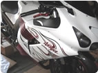
I've just removed the entire ABS system from my 2015 ZX14r track only turbo bike and I'd like to put the warning light out. The service manual pg. 16-85 shows meter pin 6 as the "abs indicator light" the wiring diagram confirms this comes directly from the abs/ecu violet wire with no other connections. The light is on and I'm trying to understand the meter logic to do this? Does the ecu ground the violet wire to keep the light off or put 12v. to it with the meter having some sort of balancing resistor that triggers the light if it doesn't see 12v. from each side? I've got an old printed circuit board and have to try to follow the circuits but have no way of telling what does what if I run into some other components. I know for sure the violet wire is currently going nowhere/open without being grounded or energized. Worst case is I'll tape the indicator but I'd much rather do it right.
Aloha for your time, Rick B...
 |
 |
 |
 |
 |
 |
Created on: 01/29/17 10:28 AM
Replies: 4
Fordtech58
Joined: 12/10/16
Posts: 179
ABS warning light meter logic?
01/29/17 10:28 AM
Hub
Joined: 02/05/09
Posts: 13968
RE: ABS warning light meter logic?
02/07/17 12:07 AM
The light is on and I'm trying to understand the meter logic to do this?
I think you know the drill; so at the connector end of the ECU, back-probe the purple wire and see how many volts are traveling thru the purple wire? At the pod end, there is a trick to pulling the wire out of the connector end rather than cutting the wire. A jeweler's loop would show the center locking tab that needs to be pressed down with a shaved down pocket screwdriver>> just for this job. If the ECU's connector looks easier to press the locking tab, who cares, the power is down = No light.
Does the ecu ground the violet wire to keep the light off or put 12v. to it with the meter having some sort of balancing resistor that triggers the light if it doesn't see 12v. from each side?
I think it goes something like this. In section 3 it shows the pin breakdown. Only a few pins receive 12v from the battery. This starts at an integrated chip's leg, but converts down to 5v for the ECU to function with sensor inputs producing well under 5v. So you can't run 12v to any other pins but 3 prongs into the ECU.
Extend your fingers out and spread them apart. Place thumbs out so they both touch. Flip one wrist and touch a pinkie to a thumb. Flip the other wrist so both pinkies touch. That's 4 moves of on and off. Say thumbs flow current, pinkies don't and head for ground. Now say the light is off when pinkies touch. This says all sensors are hooked up, no out of range are they to trigger the light. So say the one tone wheel fails, the flipflop occurs when a pinkie touches a thumb is one direction taken for one wheel. Now say the other abs sensor at the other wheel fails. Flip the wrist so this throws the code to turn the light on. Sort of see the flipping combos one turns the light on for either wheel? Or said another way:
1. Thumb to thumb = current flow waiting for ground... as if a wall socket waiting for a lamp to be plugged in.
2. Pinkie to pinkie = Ground going to ground.
3. Thumb to pinkie = Light turns on so both ground and current are connected to the LED via failed rear wheel say.
4. Pinkie to thumb = Light comes on because the front wheel tone wheel and sensor are in question.
The do it right goes something like this. What do I look like snipping a wire to shut the light down vs. pulling up the trousers and taping the light offandango.
Fordtech58
Joined: 12/10/16
Posts: 179
RE: ABS warning light meter logic?
02/07/17 8:16 PM
Well Hub, Thanks for the reply but as the first line in my post states. "I've just removed the entire ABS system" so I have no way of back probing the purple wire to check the voltage. Woulda, coulda, shoulda done that before pulling it all out... now I know. Reading the diagram and knowing it goes directly from the ABS module to the cluster with no other stops or intersections along the way tell me it's got to get some type of signal albeit power/ground/duty cycle? from the ABS. It remains on in it's open state. If I had access to another ABS bike I'd have the answer with just the windshield removed in a matter of minutes but alas I don't.
Thanks for your attempt, and love that signature. "Tormenting the motorcycling community one post at a time" Aloha, Rick B...
Hub
Joined: 02/05/09
Posts: 13968
RE: ABS warning light meter logic?
02/08/17 2:41 AM
ABS module to the cluster with no other stops or intersections along the way tell me it's got to get some type of signal albeit power/ground/duty cycle?
Pg. 12-31:
Since I opened up the book, I'll edit it this way:
"I think you know the drill; so at the connector end of the ECU, back-probe the G/Y wire and see how many volts are traveling thru the G/Y wire?"
Albeit some wires lead to a light fandango, the ECU calls the ball switching it on and off. That's what I think you missed in the wire chase. The continued on part meaning. Number 7 is waiting for that ping. Here's how this plays out diagnostic wise.
1. Short to ground = Not it.
2. Signal out of range = Not it.
3. Connector not connected = Bingo! wires dangling in the air going nowhere. See it send the code purple rain?
So as the disconnect from V to G/Y, we broke the loop from the ECU, i.e., the wire R/Y = 3 connects dangling.
So how do we trigger the light offandango... do we tie both wires out of the ECU to V?
So can we swap just the V to either R/Y and wait for the ping to turn the light off?
So are we on the same page about who is hot and who is not out of the ECU?
So do we run that safety ohm resistor so heat burns your fingers at the resistor not the ECU we turn the key on?
Signed,
NOLTT (no one likes turtle tape?) But will he listen or fry one for the team?
* Last updated by: Hub on 2/8/2017 @ 3:57 PM *
Hub
Joined: 02/05/09
Posts: 13968
RE: ABS warning light meter logic?
02/08/17 6:50 PM
Think of those 4 moves at the front and rear tone wheels. You are looking for meter logic so it more runs in the absolute this way:
1. Thumb to thumb = everyone is within spec/no short/etc., so no light on.
2. Thumb to pinkie = front wheel codes. The logic is either on or off, so on means the light is on.
3. Pinkie to pinkie = everyone is within spec so no light on.
4. Pinkie to thumb = rear wheel codes. If the front is T to T, then of course no code and now the other wheel uses the dash light this way.
Does that make sense?
So now my thinking is having to tie both wires out of the ECU if my logic says both pins are for front and rear tones. If I tie the one only, I turned off the one wheel's code at that flipflop, but the other light stays on for the other tone wheel. I'd have to look at the pin-out page to match color to the ECU's pin to know for sure.
Did that make sense?
New Post
Please login to post a response.


